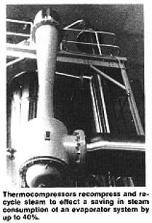
The Marriott Walker Corporation, of Birmingham, Michigan, a leading manufacturer of multiple-effect evaporator systems for the Food Industry, verifies this trend. It reports increasing interest on the part of dairy food processors in installing thermocompressors on new evaporator systems, and also in the feasibility of retrofitting existing systems with these simple devices that recompress and recycle steam.
Reduces Steam Consumption: In fact, according to A. Marriott Walker, president of the company, thermal recompression can save more than one-third of the steam and water required in a similar capacity evaporator system not using thermocompressors.
Evaporator Operation: Steam flows through a typical multiple-effect dairy evaporator in the following way. Steam enters the first effect of the evaporator at a pre-determined temperature and pressure. Having given up part of its heat in the first effect, it is routed to the second effect at a lower temperature and pressure. It then passes to the third effect at a still lower temperature and pressure. To offset these heat losses from the steam, the pressure in the vessel of each succeeding evaporator effect is reduced by steam jet ejectors, which lowers the boiling point of the milk. The last effect operates at the lowest pressure and temperature. Steam leaving the last effect is normally condensed and its energy made available for other heating purposes.
Thermal recompression is an alternative and more efficient method of reusing spent steam for greater efficiency in the evaporation phase.
 Thermal Recompression: Thermocompression, as applied to evaporators, particularly in the Food Industry, is a process by which a portion of the steam discharged from an evaporator effect is captured and compressed to a higher pressure and temperature for re-use. This is accomplished by a thermocompressor which entrains and compresses low-pressure spent steam for reuse at a higher pressure in the initial effect of a multiple-effect evaporator. A thermocompressor is similar to, and operates on, the same principle as a steam jet ejector used for producing a vacuum.
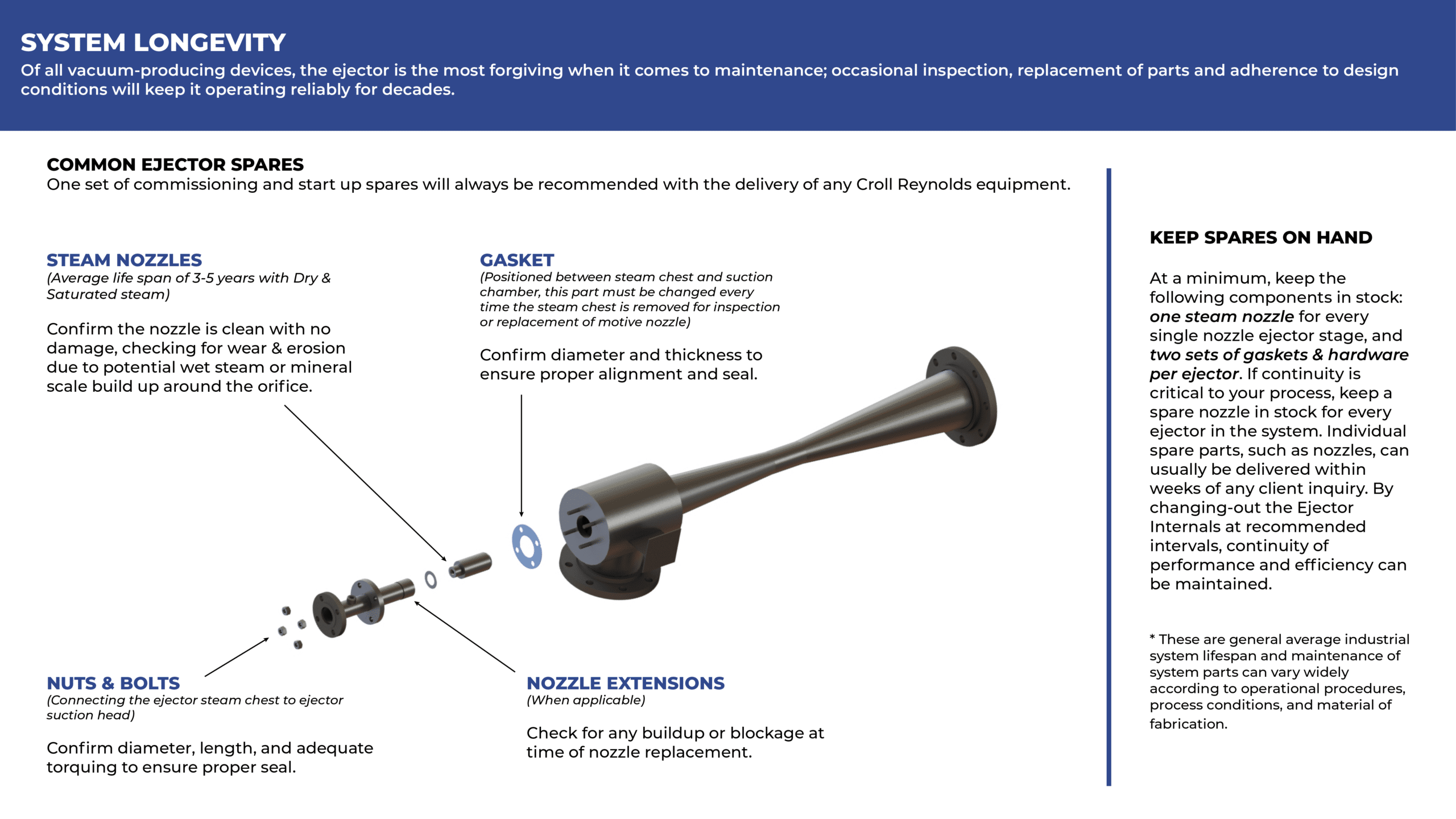
Croll Reynolds thermocompressors consist of three basic parts: nozzle, mixing chamber, and diffuser. These sections function passively to entrain and compress a low-pressure fluid, such as spent steam, to some higher pressure. The recompressed fluid can then be used elsewhere, and its heat reclaimed.
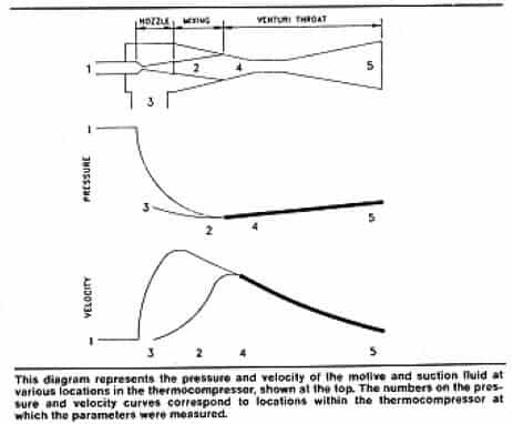
In operation, high-pressure steam, as a motivating fluid, enters and expands through the converging-diverging nozzle to the mixing chamber. Pressure drops sharply and the velocity increases rapidly as the steam leaves the nozzle. The suction fluid, low-pressure steam enters and mixes with the motivating steam in the mixing chamber. The mixture is then recompressed to an intermediate pressure as it passes through the diffuser.
The overall efficiency of the steam thermocompressor can be expressed as a function of the entrainment efficiency. Because of impact and turbulence, there is an unavoidable loss of kinetic energy when the high-velocity motive fluid entrains the slower suction fluid. The kinetic energy of the mixture that results is only a fraction of that originally possessed by the motive fluid. The fraction that is successfully transferred to the mixture through the exchange of momentum is referred to as the “entrainment efficiency.” A portion of the motive energy is absorbed by the mixture as heat and therefore produces an increase in enthalpy.
Thermal Recompression: Thermocompression, as applied to evaporators, particularly in the Food Industry, is a process by which a portion of the steam discharged from an evaporator effect is captured and compressed to a higher pressure and temperature for re-use. This is accomplished by a thermocompressor which entrains and compresses low-pressure spent steam for reuse at a higher pressure in the initial effect of a multiple-effect evaporator. A thermocompressor is similar to, and operates on, the same principle as a steam jet ejector used for producing a vacuum.
Croll Reynolds thermocompressors consist of three basic parts: nozzle, mixing chamber, and diffuser. These sections function passively to entrain and compress a low-pressure fluid, such as spent steam, to some higher pressure. The recompressed fluid can then be used elsewhere, and its heat reclaimed.
In operation, high-pressure steam, as a motivating fluid, enters and expands through the converging-diverging nozzle to the mixing chamber. Pressure drops sharply and the velocity increases rapidly as the steam leaves the nozzle. The suction fluid, low-pressure steam enters and mixes with the motivating steam in the mixing chamber. The mixture is then recompressed to an intermediate pressure as it passes through the diffuser.
The overall efficiency of the steam thermocompressor can be expressed as a function of the entrainment efficiency. Because of impact and turbulence, there is an unavoidable loss of kinetic energy when the high-velocity motive fluid entrains the slower suction fluid. The kinetic energy of the mixture that results is only a fraction of that originally possessed by the motive fluid. The fraction that is successfully transferred to the mixture through the exchange of momentum is referred to as the “entrainment efficiency.” A portion of the motive energy is absorbed by the mixture as heat and therefore produces an increase in enthalpy.
 Two Systems Compared: The value of thermal decompression can be seen with a comparison of multiple-effect evaporation by itself to multiple-effect evaporation with thermal decompression. A straight, steam-heated, triple-effect falling film evaporator processing whey would require at 270 lb/hr, 90 degrees F water at 31,5 gal/min, and 163 ft squared of heat transfer surface to produce120 lb/hr of product at 50% solids from 1,000 lb/hr of feed at 6% solids. Thus, water is evaporated at 880 lb/hr, 3.25 pounds for each pound of input steam. If thermocompression is used, steam and water requirements for the same service are reduced to 172 lb/hr and 20.3 gal/min, respectively, although the steam pressure is required to be 110 psig. The needed heat transfer surface is reduced to 154 ft squared and 5,12 pounds of water are evaporated for each pound of input steam.
The evaporator equipped with a thermocompressor uses 36% less steam and 36% less water than the straight steam evaporator when both are operating at at rate of 800 lb/hr. In addition, the evaporator equipped with a thermocompressor actually uses less heating surface than the straight steam system. This is because more evaporation is done in the first effect at low concentration, and less evaporation in the subsequent effects at higher concentration where the heat transfer coefficient is lower.
In the Food Processing Industry, product sensitivity dictates low evaporating temperatures; hence, the entire system operates under vacuum. In such plants, the boiler room usually produces steam at greater than 100 psig. Boiler room steam, therefore, must be reduced to sub-atmospheric pressure and must be desuperheated before it can be used in the evaporator, causing a substantial loss of available energy. Using thermal decompression on evaporators, high-pressure steam passes into a thermocompressor through nozzles, transforming the pressure energy that would be otherwise lost into kinetic energy of such magnitude that substantial quantitates of used low-pressure steam can be withdrawn from the evaporator and compressed for re-use. It has been found that 172 lb/hr of high-pressure steam is capable of compressing 306 lb/hr of spent steam from the first effect, resulting in a total steam feed to the evaporator of 478 lb/hr. The remainder of the falling-film triple-effect evaporator is similar to the straight steam system, except the second and third effects are smaller as a result of reduced duty.
As the Food Processing Industry continues its drive to reduce fuel costs and improve product quality, more plants will switch to multiple-effect evaporation systems. For these new systems, as well as for existing multiple-effect evaporators that can be retrofitted with thermocompressors, thermal recompression is a practical method for reducing over-all production costs.
Two Systems Compared: The value of thermal decompression can be seen with a comparison of multiple-effect evaporation by itself to multiple-effect evaporation with thermal decompression. A straight, steam-heated, triple-effect falling film evaporator processing whey would require at 270 lb/hr, 90 degrees F water at 31,5 gal/min, and 163 ft squared of heat transfer surface to produce120 lb/hr of product at 50% solids from 1,000 lb/hr of feed at 6% solids. Thus, water is evaporated at 880 lb/hr, 3.25 pounds for each pound of input steam. If thermocompression is used, steam and water requirements for the same service are reduced to 172 lb/hr and 20.3 gal/min, respectively, although the steam pressure is required to be 110 psig. The needed heat transfer surface is reduced to 154 ft squared and 5,12 pounds of water are evaporated for each pound of input steam.
The evaporator equipped with a thermocompressor uses 36% less steam and 36% less water than the straight steam evaporator when both are operating at at rate of 800 lb/hr. In addition, the evaporator equipped with a thermocompressor actually uses less heating surface than the straight steam system. This is because more evaporation is done in the first effect at low concentration, and less evaporation in the subsequent effects at higher concentration where the heat transfer coefficient is lower.
In the Food Processing Industry, product sensitivity dictates low evaporating temperatures; hence, the entire system operates under vacuum. In such plants, the boiler room usually produces steam at greater than 100 psig. Boiler room steam, therefore, must be reduced to sub-atmospheric pressure and must be desuperheated before it can be used in the evaporator, causing a substantial loss of available energy. Using thermal decompression on evaporators, high-pressure steam passes into a thermocompressor through nozzles, transforming the pressure energy that would be otherwise lost into kinetic energy of such magnitude that substantial quantitates of used low-pressure steam can be withdrawn from the evaporator and compressed for re-use. It has been found that 172 lb/hr of high-pressure steam is capable of compressing 306 lb/hr of spent steam from the first effect, resulting in a total steam feed to the evaporator of 478 lb/hr. The remainder of the falling-film triple-effect evaporator is similar to the straight steam system, except the second and third effects are smaller as a result of reduced duty.
As the Food Processing Industry continues its drive to reduce fuel costs and improve product quality, more plants will switch to multiple-effect evaporation systems. For these new systems, as well as for existing multiple-effect evaporators that can be retrofitted with thermocompressors, thermal recompression is a practical method for reducing over-all production costs.
Thermal Recompression: Thermocompression, as applied to evaporators, particularly in the Food Industry, is a process by which a portion of the steam discharged from an evaporator effect is captured and compressed to a higher pressure and temperature for re-use. This is accomplished by a thermocompressor which entrains and compresses low-pressure spent steam for reuse at a higher pressure in the initial effect of a multiple-effect evaporator. A thermocompressor is similar to, and operates on, the same principle as a steam jet ejector used for producing a vacuum.
Croll Reynolds thermocompressors consist of three basic parts: nozzle, mixing chamber, and diffuser. These sections function passively to entrain and compress a low-pressure fluid, such as spent steam, to some higher pressure. The recompressed fluid can then be used elsewhere, and its heat reclaimed.
In operation, high-pressure steam, as a motivating fluid, enters and expands through the converging-diverging nozzle to the mixing chamber. Pressure drops sharply and the velocity increases rapidly as the steam leaves the nozzle. The suction fluid, low-pressure steam enters and mixes with the motivating steam in the mixing chamber. The mixture is then recompressed to an intermediate pressure as it passes through the diffuser.
The overall efficiency of the steam thermocompressor can be expressed as a function of the entrainment efficiency. Because of impact and turbulence, there is an unavoidable loss of kinetic energy when the high-velocity motive fluid entrains the slower suction fluid. The kinetic energy of the mixture that results is only a fraction of that originally possessed by the motive fluid. The fraction that is successfully transferred to the mixture through the exchange of momentum is referred to as the “entrainment efficiency.” A portion of the motive energy is absorbed by the mixture as heat and therefore produces an increase in enthalpy.
Two Systems Compared: The value of thermal decompression can be seen with a comparison of multiple-effect evaporation by itself to multiple-effect evaporation with thermal decompression. A straight, steam-heated, triple-effect falling film evaporator processing whey would require at 270 lb/hr, 90 degrees F water at 31,5 gal/min, and 163 ft squared of heat transfer surface to produce120 lb/hr of product at 50% solids from 1,000 lb/hr of feed at 6% solids. Thus, water is evaporated at 880 lb/hr, 3.25 pounds for each pound of input steam. If thermocompression is used, steam and water requirements for the same service are reduced to 172 lb/hr and 20.3 gal/min, respectively, although the steam pressure is required to be 110 psig. The needed heat transfer surface is reduced to 154 ft squared and 5,12 pounds of water are evaporated for each pound of input steam.
The evaporator equipped with a thermocompressor uses 36% less steam and 36% less water than the straight steam evaporator when both are operating at at rate of 800 lb/hr. In addition, the evaporator equipped with a thermocompressor actually uses less heating surface than the straight steam system. This is because more evaporation is done in the first effect at low concentration, and less evaporation in the subsequent effects at higher concentration where the heat transfer coefficient is lower.
In the Food Processing Industry, product sensitivity dictates low evaporating temperatures; hence, the entire system operates under vacuum. In such plants, the boiler room usually produces steam at greater than 100 psig. Boiler room steam, therefore, must be reduced to sub-atmospheric pressure and must be desuperheated before it can be used in the evaporator, causing a substantial loss of available energy. Using thermal decompression on evaporators, high-pressure steam passes into a thermocompressor through nozzles, transforming the pressure energy that would be otherwise lost into kinetic energy of such magnitude that substantial quantitates of used low-pressure steam can be withdrawn from the evaporator and compressed for re-use. It has been found that 172 lb/hr of high-pressure steam is capable of compressing 306 lb/hr of spent steam from the first effect, resulting in a total steam feed to the evaporator of 478 lb/hr. The remainder of the falling-film triple-effect evaporator is similar to the straight steam system, except the second and third effects are smaller as a result of reduced duty.
As the Food Processing Industry continues its drive to reduce fuel costs and improve product quality, more plants will switch to multiple-effect evaporation systems. For these new systems, as well as for existing multiple-effect evaporators that can be retrofitted with thermocompressors, thermal recompression is a practical method for reducing over-all production costs.
Installation of a thermocompressor at McGuiness Distillers’ Toronto plant has provided the distiller with a method of capturing and recompressing steam for reuse while simultaneously reducing energy costs in the still operation.
The four columns that produce spirit use about 14,000 lbs. of steam/hour. The largest user of steam is the beer column which strips the alcohol, produced during fermentation, from the mash. The stillage leaves the base of the column at about 220 degrees F and is then passed through a centrifuge to remove corn fines which are sold as cattle feed. The need to reduce steam consumption and the high temperature of this effluent led to the idea of recovering this heat by the principle of a jet ejector system. An ejector is a simplified type of vacuum pump or compressor which has few moving parts. It consists essentially of a steam nozzle that discharges a high velocity jet across a suction chamber that is connected to the equipment to be evacuated. The gas, in this case steam vapor, is entrained by the steam and carried into a ventri-shaped diffuser which converts the velocity energy of the steam into pressure energy.
The idea of a thermocompressor system for application at McGuinness was the responsibility of Mike Delevante (technical services manager). He was assisted by Gord Dine (plant manager) and Charlie Hayler who was in charge of the project. Consultation with Stone & Webster led to the installation of the system which utilizes a Croll Reynolds Jet Ejector, for evacuating vapor from the hot stillage that passes through a large vacuum tank at the base of the column.
The Croll Reynolds ejector is mounted atop of a 500-gallon tank and high pressure steam (100 psi) is passed through the ejector. Liquid at a temperature of 220 degrees F passes from the base of the still through the tank at a constant rate. The vacuum created by the ejector lowers the temperature in the vacuum tank thus releasing low pressure steam vapor which is entrained by the high pressure steam. The motive steam plus entrained vapor is then used to heat the still and the net result is that less motive steam is used for the still operation.
It has been found that, properly designed, an ejector can “pick up” about 25% of the steam required from the effluent, and in the case cited, a steam saving of 1500 lb/hr has been realized on the beer column. The other advantage is that there is a resulting temperature drop in the effluent and the stillage no longer has to be cooled prior to going to the centrifuges.
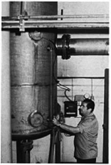 The thermocompressor steam conservation system was made operational after the 1981 summer shutdown. A flash tank, Croll Reynolds ejector, two pumps, some piping changes and instrumentation were all that was required. The components were all started on the first day of operation and the operators adapted quickly to the new system which does not increase the complexity of starting up the column.
The ejector consists of five basic parts: a variable spindle-operated nozzle, mixing chamber, diffuser, steam chest and spindle actuator. The 6′ x 6′ x 2 1/2′ spindle nozzle is a special feature which allows for variable operation without any instability or loss of efficiency.
Instead of a standard fixed orifice, which can also be adapted to this operation, the nozzle and spindle assembly combines a rounded entrance orifice with a straight section into which a tapered spindle is guided. Its operation is very much like that of a needle valve.
Spindle-operated units are used where suction and discharge pressure vary greatly, requiring large compensating changes in motive fluid flow. Such is the case at McGuinness where the motive steam is at a pressure of 100 psi and the user steam is at a pressure of 8 psi. In this way higher efficiencies are obtained by maintaining high motive pressures rather than by wasteful throttling.
Summary & Results: The McGuinness distillation system is a practical demonstration of the principle of thermal recompression. The high pressure steam passing through the thermocompressor captures the heat (in the form of steam vapor) that would otherwise be lost. This becomes Kinetic energy of such magnitude that a substantial quantity of low pressure steam is recovered and compressed for reuse in the beer column.
Our Croll Reynolds system resulted in a 25% reduction in live steam demand and provided us with a maintenance free system with a less than two year payback. It has been our most practical system for reducing overall production and energy costs.
The thermocompressor steam conservation system was made operational after the 1981 summer shutdown. A flash tank, Croll Reynolds ejector, two pumps, some piping changes and instrumentation were all that was required. The components were all started on the first day of operation and the operators adapted quickly to the new system which does not increase the complexity of starting up the column.
The ejector consists of five basic parts: a variable spindle-operated nozzle, mixing chamber, diffuser, steam chest and spindle actuator. The 6′ x 6′ x 2 1/2′ spindle nozzle is a special feature which allows for variable operation without any instability or loss of efficiency.
Instead of a standard fixed orifice, which can also be adapted to this operation, the nozzle and spindle assembly combines a rounded entrance orifice with a straight section into which a tapered spindle is guided. Its operation is very much like that of a needle valve.
Spindle-operated units are used where suction and discharge pressure vary greatly, requiring large compensating changes in motive fluid flow. Such is the case at McGuinness where the motive steam is at a pressure of 100 psi and the user steam is at a pressure of 8 psi. In this way higher efficiencies are obtained by maintaining high motive pressures rather than by wasteful throttling.
Summary & Results: The McGuinness distillation system is a practical demonstration of the principle of thermal recompression. The high pressure steam passing through the thermocompressor captures the heat (in the form of steam vapor) that would otherwise be lost. This becomes Kinetic energy of such magnitude that a substantial quantity of low pressure steam is recovered and compressed for reuse in the beer column.
Our Croll Reynolds system resulted in a 25% reduction in live steam demand and provided us with a maintenance free system with a less than two year payback. It has been our most practical system for reducing overall production and energy costs.