Figure 1. In total, this illustration represents a four-stage ejector system with two surface-contact intercondensers. A simple single-stage system would comprise only the section in the outlined box. In either case, motive force is provided by steam jets, which draw vapor from a vessel and through the system. The condensers act to reduce the load on the next ejector. 
Steam jet ejectors offer a simple, reliable means of producing vacuum, and have a low installed cost as well. They are commonly found in process plants having available steam. The vacuum produced is useful for many processes, including evaporation, cooling, hydration, crystallization, deaeration and filtration.
Through the simplicity of its construction (Figure 1), the steam-jet ejector provides many years of troublefree operation. When a problem does occur, many plant personnel do not have the experience to effectively troubleshoot an ejector system, and precious production time is lost.
For example, a loss of vacuum in a multistage ejector system might have many plant personnel disassembling the first-stage ejector booster, on the assumption that one must check a unit from inlet to outlet. In fact (as will be shown later in this article), this is the last place to look. Fortunately, downtime can be kept to a minimum when a logical sequence of steps — a checklist — is followed to locate the source of trouble.
Ejector Basics: Â Ejectors can be classified as single-stage or multistage. Multistage ejectors may be further divided into condensing or noncondensing types. The single-stage ejector, the simplest and most common type, is generally recommended for pressures ranging from atmospheric pressure (30 in. Hg absolute) to 3 in. Hg abs. Discharge is typically at or near atmospheric pressure. The boxed section of Figure 1 shows a single-stage system. The effects of injected steam on process vapors is shown in figure 4. Multistage noncondensing ejectors (MNEs) are used to produce suction pressures lower than 3 or 4 in. Hg abs. Steam consumption in an MNE is relatively high. Each successive stage is required to handle the load plus the motive steam from the previous stage. MNEs are frequently used when low first cost is more important than long-range economy. They are also used for intermittent service or when condensing water is not available. MNEs are usually two-stage, although six-stage units have been used successfully.
Multistage condensing ejectors (MCEs) are available in two through six stages. Intercondensers (surface or direct-contact) between stages condense steam from the preceding stage, reducing the load to be compressed in the succeeding stage. A multistage system is shown in Figure 1.
Four-, five- and six-stage ejectors are used to achieve suction pressures as low as 5 µm Hg abs. Under such vacuum conditions, pressure between the preliminary stages is too low to permit condensation of ejector steam, and only the final two stages are fitted with condensers. MCEs remove condensable vapor ahead of a given ejector stage. They also permit use of a smaller ejector, and a reduction in the amount of steam required. Condenser nomenclature is determined by the corresponding operating conditions and functions.
Precondensers are used when the absolute pressure of the process is sufficiently high to allow condensation at the temperature of the available water supply. Noncondensables are removed from the precondenser by one or more ejector stages. Condensers or inter-condensers liquefy process vapor and motive steam from one or more preceding booster ejectors. Aftercondensers condense steam discharging from the last-stage ejector, generally at atmospheric pressures.
There are two basic types of condensers — direct-contact and surface-contact. In direct-contact (countercurrent, barometric design) condensers, cooling water is mixed directly with the vapor to be condensed, then discharged to atmosphere through a barometric leg or tailpipe of sufficient length to overcome the atmospheric pressure. A means of cleaning up or otherwise disposing the water that has become contaminated by process material is often required. The surface-contact condenser permits main-condenser cooling water to be used as cooling water through inter- and aftercondensers, for energy and process-water conservation.
Where To Start: When a vacuum problem arises there are several preliminary checks that should be made on an ejector system before components are disassembled. First, is the system design data readily available? Most ejector systems are custom-designed to operate at a specified vacuum, given process loads, minimum available steam pressure, maximum steam temperature, maximum discharge pressure and maximum water temperature. It is impossible to evaluate the complete system unless the manufacturer’s design parameters are known.
A data sheet can be obtained from the manufacturer of the ejector system and should list the design vacuum, capacity, interstage ejector vacuums, motive steam pressure and temperature, condenser water-inlet and -outlet temperatures, and discharge pressure. Critical dimensions such as the diameters of the ejector nozzle orifice and the diffuser bore should also be know.
Once the design data are located, there is an ordered series of steps to take in isolating ejector problems. One should check:
- Gauges
- Steam
- Water
- Process loads
- Field report and process logs
Pay Attention To Instruments: When troubleshooting the ejector system, accurate pressure and temperature measurements are needed to quickly locate the source of the problem. Therefore, a check of the system’s instrumentation is a necessity. All vacuum, pressure, and temperature gages should be calibrated or replaced. A malfunctioning vacuum gage may be found to be the entire vacuum “problem.”
If the vacuum gage is several feet or more from the ejector system, check the line running from the system to the gage for air leakage. It would take a very small amount of air leakage in an instrument vacuum line to throw off the measurement. If leakage is suspected, connect the test gage directly to the ejector and compare vacuum measurements. If there is a valve in the vacuum line, close it and observe the vacuum line, close it and observe the vacuum gage. If it slowly loses vacuum, air leakage is occurring.
For troubleshooting purposes, overall, an absolute pressure gage is preferred over a common vacuum gage. A common vacuum gage that reads in units of inches of mercury vacuum is food for rough measurements by operators, but this gage does not five the accuracy needed for a system analysis. Besides relative inaccuracy, vacuum gages require a barometric pressure measurement to determine an ejector’s vacuum in units of inches of mercury absolute. There are a variety of suppliers of such absolute-pressure gages.
 Typically, an absolute mercury manometer is used for measuring the vacuum in the Y and Z stages (Figure 2). It can be flooded with water and still give a relatively accurate reading.
Replacement mercury U-tubes are also inexpensive, and are available from various suppliers. Mercury-free units are also available, and are typically used for the higher-vacuum ejectors such as W or X stages. There are also many manufacturers of electronic vacuum gages that offer very accurate and portable instruments. The gages are well worth the investment and should be kept in stock only to be used when troubleshooting ejector systems.
Steam-pressure gages should be located on the steam chest of the ejectors or as close to the unit as possible. It is important to know the actual operating steam pressure since an ejector of critical-flow design (suction pressure less than half discharge pressure) will not operate properly when even a few psi below its design motive pressure. Compound steam pressure gages are recommended since they will not be damaged when exposed to vacuum.
Steam: Motive steam plays probably the most important role in the operation of a steam jet ejector. Since internal dimensions are fixed, the ejector is designed for only one steam condition. When the steam condition changes there will be a change in the operation and efficiency of the ejector.
In a critical-flow ejector a decrease in steam pressure of just a few psi will result in a broken or unstable vacuum. An increase in steam pressure above design will not have a noticeable effect in the operation of an ejector unless the increase is significant (>25%).
Besides wasting steam, excess motive pressure tends to choke the venturi with steam, thereby decreasing the suction capacity of the ejector. Note too that the performance of ejectors designed for saturated steam will be adversely affected if operated with super-heated steam.
The specific volume of steam increases with increasing temperature, which may require an increase in pressure to maintain required steam flow. Otherwise, as in the case of low steam pressure, the manufacturer must be consulted for a redesign of the ejectors.
Excess moisture in steam is one of the most common problems found in ejectors. Wet steam causes poor performance and, depending on the degree of wetness, can permanently damage an ejector in a very short period of time. A steam quality of less than 2% moisture is tolerable with most moderate vacuum systems. However, ejectors designed for a vacuum of 5 mm Hg abs or less should have steam that is completely dry or with a few degrees of superheat.
A telltale sign of wet steam is a fluttering needle on a steam pressure gage during operation. But the only sure way to determine quality of steam is to test it with a throttling calorimeter. This is a constant-enthalpy device that measures steam pressure and temperature. When used in combination with a Mollier chart, a reading of steam quality is obtained.
If steam is found to be wet, a steam separator should be installed in the steam line as close to the ejector as possible. Keeping all steam piping, and the steam separator, completely insulated will also help prevent the formation of wet steam.
Water: Multiple-stage ejector systems will normally include condensers between some or all stages. Condenser designs are based on maximum water temperature and available flow. When inlet water temperature increases above design maximum, loads to the following stage increase, resulting in a poorer vacuum at that stage. If the affected stage is the last (Z) stage, then the vacuums of all the preceding stages could also be affected.
The water temperature rise across a surface-contact condenser should be compared with design. A temperature rise larger or smaller than design could be an indication of a flow problem or fouling.
In direct-contact condensers, high or low water flowrates can cause problems in the vacuum system. High water flow could flood the condenser, increasing pressure drop, and therefore, the back pressure on the stage discharging into it. Low water flow may not be distributed properly, allowing condensable load to bypass into the following ejector and resulting in a poor vacuum.
Figure 4. The three basic parts of an ejector are the nozzle, mixing chamber and diffuser. High-pressure motive fluid passes through the nozzle, expands in the mixing chamber (where pressure is converted to fluid velocity), and passes through the venturi throat of the diffuser. Process fluid enters the suction port and is drawn into the mixing chamber. The curves show the changes in velocity (above) and pressure (below) of the motive fluid (blue) and Process fluid (magenta).
Process Loads: A change in process load will have a direct effect on the ejector system. Ejectors operate over a unique capacity curve, and any increase in load will result in a higher absolute pressure. An increase in noncondensables will travel through the system, affecting the following ejector stages. Discharge pressures of each stage will increase to the point of a breakdown in operation. As in the case of a changed steam condition, a change in process load will require redesign by the manufacturer, if design vacuum is to be maintained.
Check The Logs: Manufacturers’ field service reports or process logs may offer clues to present operational problems. the symptoms of a vacuum problem may be similar to a past problem outlined, with solutions, in a service report. Process logs may also indicate problems with steam pressure or changes in process conditions that will have a direct effect on the vacuum system.
Now Look At The Process: If the preliminary checklist is completed with no obvious problems found, the next step is to determine whether the problem lies in the ejector system or the process. The steps remaining to be considered are: no-load vacuum test (single- or multistage) and an internal inspection.
The best way to determine if the vacuum problem lies in the ejector system or the process is to isolate and test the ejector separate from the process. The standard method of testing an ejector is to attach a blank, or blind flange, on the suction flange of the ejector and measure the vacuum at no-load conditions. A stable no-load vacuum is more difficult for an ejector to reach than a point under load conditions, simply because there is a greater suction-to-discharge pressure differential.
If the no-load vacuum measures the same as the manufacturer’s test, then it is reasonably safe to assume that the ejector is working at its design load point. The problem may lie upstream from the suction of the ejector- possibly an increase in air leakage or process load. It should be noted that unless specified, an ejector may not have a stable vacuum at no-load even though it works at its design load.
Figure 5. This gage, known as a piccolo, has calibrated orifices to check vacuum quality.
To test an ejector at its design load point involves metering the design load into the suction of the ejector. Use a calibrated orifice or a series of orifices (such as can be found on an instrument known as a piccolo — Figure 5), and then compare the measured vacuum to the design vacuum. A curve can be plotted and compared with the manufacturer’s. This procedure should be considered only after all other tests are exhausted. (The manufacturer should be consulted for the proper field testing procedure if a test under design load conditions is desired.)
If the ejector does not obtain the manufacturer’s tested no-load vacuum, the ejector should then be disassembled and internally inspected. No-load testing is easily accomplished on a single-stage ejector system, but a multistage ejector system must be evaluated by checking the last stage first.
Multistage, No-Load Vacuum: Â Typically, a multistage ejector system is started up backwards from the last (Z) stage to the first. The Y stage cannot operate properly until the Z stage is working, the X stage will not work unless the Y and Z are operating, and so on.
Troubleshooting a multistage ejector system should also proceed in this back-to-front order. Check the vacuum of each stage during process load conditions, and compare it to its design value. When the measured vacuum of a stage is worse than its design, the cause of the problem at that stage must be found and corrected before proceeding any further.
The next step is to performance-test the stage in question by checking its no-load vacuum. For example, if the stage being checked is the Y stage of a three-stage ejector system, a blank should be installed on the Y suction flange. Since the Y stage is designed to discharge to a vacuum created by the Z stage, the Z stage, and intercondenser if present, must operate simultaneously during this test.
With the Y stage steam valved off, first check and record the Z stage no-load vacuum to be sure it is meeting the manufacturer’s tested value. Then, with the vacuum gage still connected to the Z stage, turn the Y stage steam on. If the Z stage vacuum steadily falls off, the intercondenser is most likely the cause of trouble and should be inspected.
As mentioned in the preliminary checklist, a condenser temperature rise much greater or less than design may be an indication of a water-flow problem. A water-flow problem can result in a higher condenser temperature and an overloading of the following stage with uncondensed vapor. In this case, as the Z stage falls off, the Y stage vacuum would follow.
Examples of direct-contact condenser problems include: a blocked tailpipe, air leakage into tailpipe, damaged water distributor, or a plugged water nozzle. Surface condenser problems include: a blocked drain, air leakage into tailpipe, or split or fouled tubes.
If the Z stage vacuum is within specifications, move the vacuum gage to the Y stage. If the Y stage vacuum measures exactly the same as that of the Z stage, a blocked Y stage nozzle may be the cause. However, at this point, if the Y stage vacuum does not measure reasonably close to the manufacturer’s tested no-load value, the stage should be disassembled for internal inspection.
Finding the Y and Z stage vacuums within specifications, remove the blind flange from the Y stage suction and repeat the procedure at the X stage. It is important to remember that each stage must meet its design vacuum before continuing the testing.
At times it may be impractical to make and install a blind flange on the suction connection of an ejector due to the size of the unit. In most cases, however, these larger stages will be the W or X. If the no-load testing has ruled out the Y and Z stages and the condensers ass possible causes of the vacuum problem, and internal inspection of these larger stages may be the more practical step to follow.
Internal Inspection: There are several things to look for when performing internal inspection of an ejector. Usually any kind of corrosion or erosion that is obvious to the eye and touch will affect the performance of an ejector. An indication of wet steam will show as lines (“wiredrawing”) etched up and down the inside of the steam nozzle. The point along the diameter where the steam contacts the venturi is another location that may be gouged due to wet steam.
Steam leaking around the nozzle puts an artificial load on that stage, resulting in poor vacuum. Leakage of this sort should be noticeable as a discoloration where the nozzle seats on the steam chest, or as erosion of the nozzle threads. A process that causes corrosion or buildup of material on the internals of an ejector will also effect the performance of that unit.
Critical dimensions such as the nozzle orifice or venturi bore diameter, obtained from the manufacturer, will enable a measurement of dimensions to determine extent of wear. Part numbers of the various ejector components should be checked to ensure they are in the right unit. Many ejector parts, and complete stages, are physically interchangeable and care must be taken not to mix them.
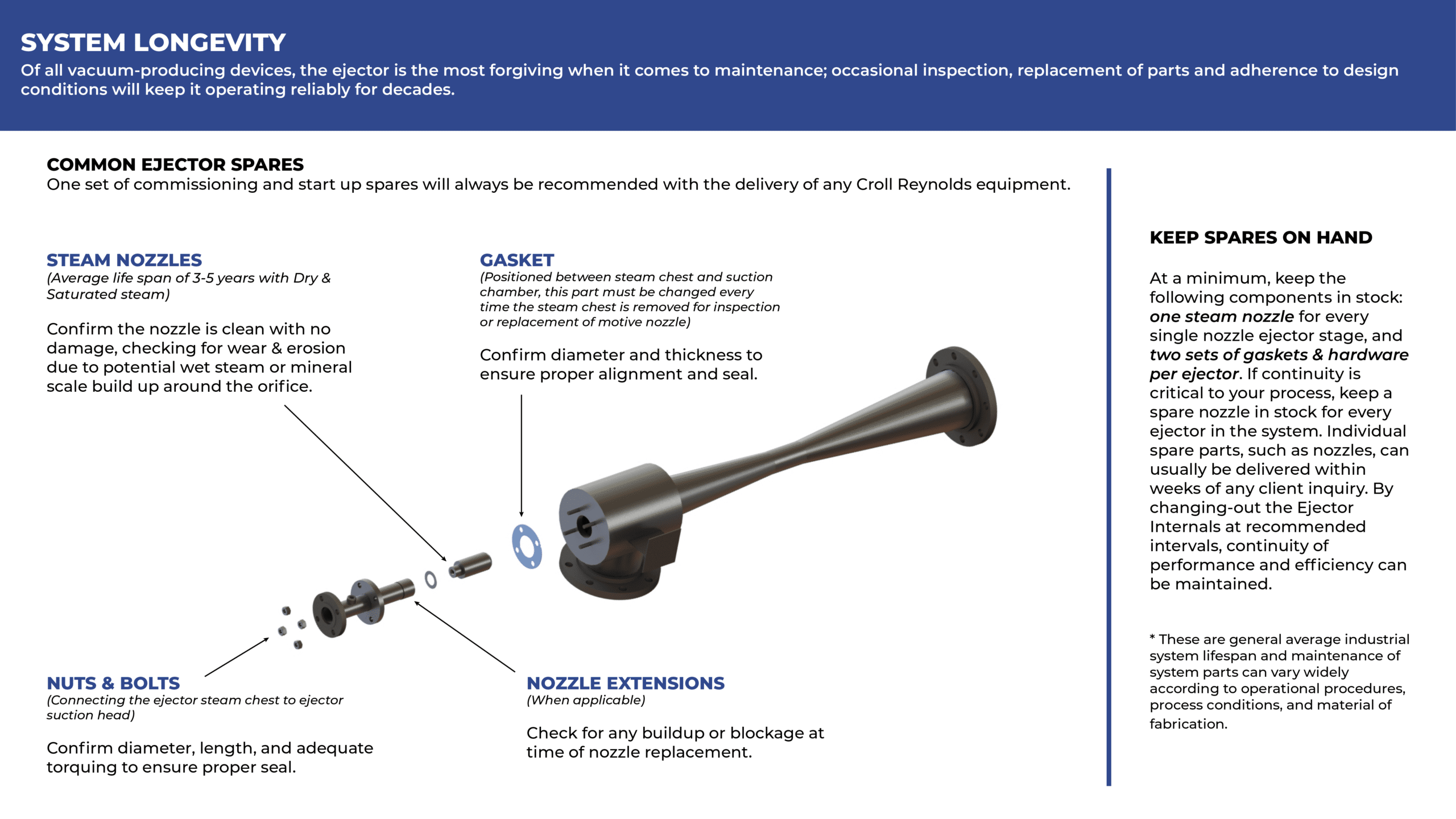
Keep Spares On Hand: At a minimum, keep at least the following components in stock:
- One steam nozzle for every single nozzle ejector stage
- One diffuser for every stage, at least in sizes through 6 in. — higher, if continuity of service is critical
If continuity of service is important to a process, keep a spare steam nozzle in stock for every size ejector in the system. Spare diffusers are also worthwhile to keep in stock, especially for smaller systems. While it is theoretically possible for the plant engineer to recondition these parts, the practice is not recommended because critical dimensions may be altered.
Since most nozzles are relatively inexpensive they should be considered sacrificial; if wear is evident they may be discarded and easily replaced. A complete Z stage should be kept in stock for important systems in critical operations.
If these simple tips fail, don’t despair. Check the nameplate and call the manufacturer. A condition may be new to you, but chances are the manufacturer has seen it, and corrected it, many times before. Since troubleshooting an ejector system is quite straightforward, suppliers can usually work with you over the phone to get the problem corrected. Experienced service people estimate that at least 50% or more of the troubles referred to them can be solved over the phone.
Of all vacuum-producing devices, the steam-jet ejector is the most forgiving. Occasional inspection, replacement of parts, and adherence to design conditions will keep it operating reliable for many years. Knowledge of these simple procedures for avoiding trouble, and locating it if it does occur, will save time and product in you plant.
Edited by Nicholas Basta