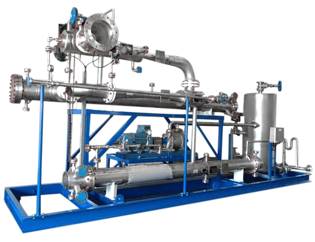
Hybrid Ejector Vacuum System
Hybrid Ejector Vacuum System
Liquid-ring pumps within multi-stage systems reduce steam consumption
About
A hybrid vacuum system serves the same function as a steam jet vacuum system; the only difference is that it incorporates single or two stage liquid-ring vacuum pumps; effectively replacing the final ejector and inter/after condenser stages of a conventional multi-stage system.
Liquid Ring vacuum pumps are rotating, positive displacement pumps that can reduce steam consumption and can eliminate the need for high-pressure boilers. The addition of liquid ring pumps allows for lower pressure steam to be utilized by deeper vacuum stage ejectors with negligible impact on system performance. Liquid ring pumps can be configured in three different arrangements based on the process requirement: once through, and partial or full recirculation. The liquid ring pump consumes electrical power instead of steam pressure to raise discharge pressure from the lowest vacuum ejector/intercondenser to atmospheric pressure. Hybrid systems can handle a wide range of gasses, vapors, particular and contaminants without implementing filter separators or traps.
Advantages
These are the primary advantages of installing hybrid systems of traditional multi-stage systems are:
- Reduced utility consumption.
- Operates using lower pressures steam
- Can be easily installed at ground level
How it works
Ejectors use converging-diverging nozzle technology to convert potential energy into kinetic energy. These energy transfers operate according to the jet vacuum principle, which illustrates the inverse relationship of potential and kinetic energy in supersonic, sonic, or subsonic flows; as the velocity of a moving fluid (liquid or gas) increases, the pressure within the fluid decreases. When the pressure energy (aka potential energy) of low-velocity steam flows through a nozzle, the result is high-velocity, low-pressure steam.
The momentum of this supersonic, saturated steam forces displacement in the steam chest as it exits the nozzle. In this scenario steam is the “motive fluid” that creates a localized vacuum in the steam chest (aka suction chamber).
The low-pressure region within the steam chest then entrains a “suction fluid” (process vapor and or/air) through a connecting inlet. The high velocity motive fluid and low-pressure suction fluid mix freely as they flow through the diffuser, where the mixture experiences a shockwave transition back to a subsonic state.
By temporarily reducing the stream’s momentum, this change in velocity creates another, subsequent increase in pressure to propel the combined stream into the next stage of the vacuum system. The internal geometry, precise dimensions, and arrangement of ejector components are expertly engineered to govern velocity/pressure conversions.
The diffuser’s geometry moderates the outflow conditions of the mixed stream to discharge for the ejector stage. The diffuser’s output is then available to be cooled, condensed, and pumped through a condenser, compressing the fluids so that the motive energy can be utilized in compressing the process vapors to the final discharge pressure required at the final stage of the vacuum system. In the last stage of an ejector system, any remaining vapors at the discharge stage have been treated for environmentally safe release into the atmosphere.
Use cases
- Chemical –product distillation, drying, flash cooling and more
- Oil and Gas – refinery processes, product distillation and more
- Power Plants – removal of non-condensable gas for turbine efficiency
- Steel – refinery processes, product degassing and more
- Pharmaceuticals – controlled conditions for chemical processes
- Food and Beverage – product crystallization, evaporation and more