Steam-jet vacuum systems combine ejectors, condensers and interconnecting piping to provide relatively low-cost and low-maintenance vacuum pumping. These systems operate on the ejector-venturi principle, which relies on the momentum of a high-velocity jet of steam to move air and other gases from a connecting pipe or vessel.
During system design, critical decisions must be made regarding process conditions, component orientation and layout. A reliable source of steam and cooling water must be available, and provisions must be made to carry out condensate removal under vacuum. Finally, the appropriate monitoring and control instrumentation must be specified. Specific guidelines should be followed during equipment layout and installation, to optimize system performance.
Equipment Arrangement: Ejectors — An ejector is a type of vacuum pump or compressor. Since an ejector has no valves, rotors, pistons or other moving parts, it is a relatively lowcost component, is easy to operate and requires relatively little maintenance.
In a steam-jet ejector, the suction chamber is connected to the vessel or pipeline that is to be evacuated under vacuum. The gas that is to be induced into the suction chamber can be any fluid that is compatible with the steam and the components’ materials of construction.
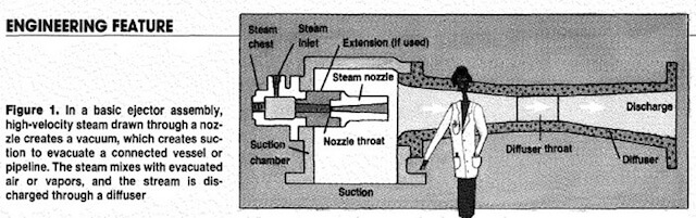
The steam nozzle discharges a high velocity jet across the suction chamber. This steam jet creates a vacuum, which extracts air or gas from the adjoining vessel. As these gases are entrained in the steam, the mixture travels through the ejector, into a venturi-shaped diffuser. In the diffuser, its velocity energy is converted into pressure energy, which helps to discharge the mixture against a predetermined back pressure, either to atmosphere or to a condenser (Figure 1).
 Since the capacity of a single ejector is fixed by its dimensions, a single unit has practical limits on the total compression and throughput it can deliver. For greater compression, two or more ejectors can be arranged in series. For greater throughput capacity of gas or vapor, two or more ejectors can be arranged in parallel.
In a multi-stage system, condensers are typically used between successive ejectors. By condensing the vapors before sending the stream on to the next stage, the vapor load is reduced. This allows smaller ejectors to be used, and reduces steam consumption.
Precondensers can be added to reduce the load on the first-stage ejector, and allow for a smaller unit. An aftercondenser can also be added, to condense vapors from the final stage. Adding an aftercondenser will not affect overall system performance, but may ease disposal of vapors.
Ejectors may be installed at any angle. However, to keep condensate and any entrained solids from collecting, low points in the vacuum piping system should be avoided during design and installation.
Provisions should be made to ensure proper drainage of the ejector bodies, since any condensed steam or process vapors may reduce throughput capacity. Drain valves installed at low points can be either manual or automatic, depending on customer requirements, and the drain cycle must relate to the type of process: Batch systems should be drained before each cycle, while continuous processes may be drained during operation if needed.
In most cases, the ejector is an integral part of a steam-jet vacuum system, but it is not intended to provide physical support for the system. Adequate piping support should be provided to minimize external loads on the ejectors, since any misalignment will adversely affect system performance. In fact, care must be exercised during system design, so that external loads caused by thermal movement and mechanical loading are minimized.
If the ejector or piping is steam jacketed to prevent ice buildup, its orientation will affect the operation and drainage of the jackets. To keep the jackets from filling with condensate, all inlet and outlet piping should be installed so that the jacket can be sufficiently drained.
In certain systems, vacuum processes produce varying amounts of solid carryover, which can deposit inside the ejector system. During ejector placement, access for cleaning must be maintained, especially if the potential for deposits exists.
Condensers
In multi-stage systems, intercondensers are used between successive ejector stages to reduce the vapor load on later stages. These units condense steam and condensable vapors, and cool air and other non-condensable vapors. Typically, a steam-jet vacuum system uses either a direct contact (or barometric) condenser, or a surface condenser, typically a shell-and-tube heat exchanger.
For optimal performance, direct-contact condensers must be installed upright and plumb. When the condenser is mounted at barometric elevation (Table, p. 120), drainage by gravity is induced through a sealed tailpipe or drainage leg. Such a condenser must be placed at a height that is sufficient to prevent flooding under normal operation. Water inlet and outlet piping must be sized according to design flow rates.
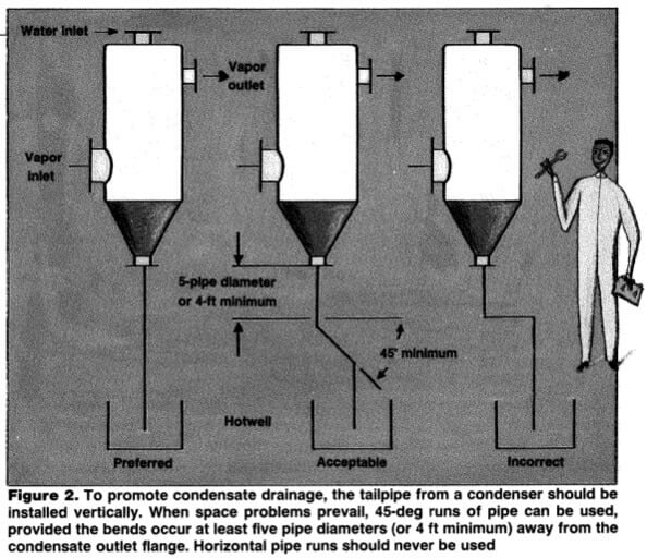
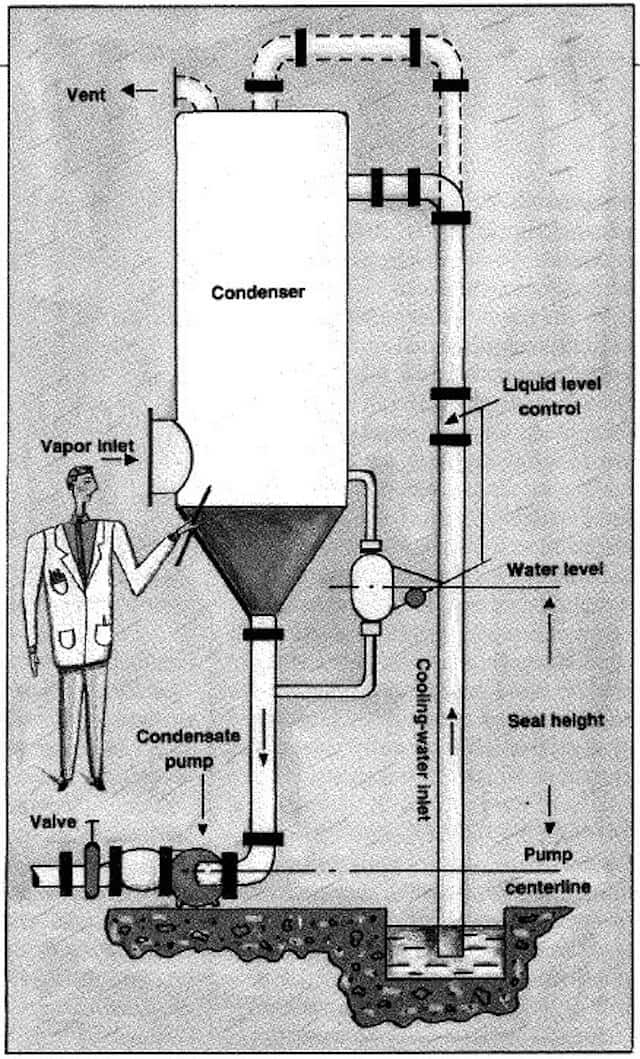
In a direct-contact condenser, the drainage lines or tailpipes should be installed vertically, and should run to a hotwell or seal tank (Figure 2). All tailpipes connected to inter- and aftercondensers must run separately to the hotwell to prevent recirculation of noncondensable vapors. Condensate removal is discussed below.
Since the capacity of a single ejector is fixed by its dimensions, a single unit has practical limits on the total compression and throughput it can deliver. For greater compression, two or more ejectors can be arranged in series. For greater throughput capacity of gas or vapor, two or more ejectors can be arranged in parallel.
In a multi-stage system, condensers are typically used between successive ejectors. By condensing the vapors before sending the stream on to the next stage, the vapor load is reduced. This allows smaller ejectors to be used, and reduces steam consumption.
Precondensers can be added to reduce the load on the first-stage ejector, and allow for a smaller unit. An aftercondenser can also be added, to condense vapors from the final stage. Adding an aftercondenser will not affect overall system performance, but may ease disposal of vapors.
Ejectors may be installed at any angle. However, to keep condensate and any entrained solids from collecting, low points in the vacuum piping system should be avoided during design and installation.
Provisions should be made to ensure proper drainage of the ejector bodies, since any condensed steam or process vapors may reduce throughput capacity. Drain valves installed at low points can be either manual or automatic, depending on customer requirements, and the drain cycle must relate to the type of process: Batch systems should be drained before each cycle, while continuous processes may be drained during operation if needed.
In most cases, the ejector is an integral part of a steam-jet vacuum system, but it is not intended to provide physical support for the system. Adequate piping support should be provided to minimize external loads on the ejectors, since any misalignment will adversely affect system performance. In fact, care must be exercised during system design, so that external loads caused by thermal movement and mechanical loading are minimized.
If the ejector or piping is steam jacketed to prevent ice buildup, its orientation will affect the operation and drainage of the jackets. To keep the jackets from filling with condensate, all inlet and outlet piping should be installed so that the jacket can be sufficiently drained.
In certain systems, vacuum processes produce varying amounts of solid carryover, which can deposit inside the ejector system. During ejector placement, access for cleaning must be maintained, especially if the potential for deposits exists.
Condensers
In multi-stage systems, intercondensers are used between successive ejector stages to reduce the vapor load on later stages. These units condense steam and condensable vapors, and cool air and other non-condensable vapors. Typically, a steam-jet vacuum system uses either a direct contact (or barometric) condenser, or a surface condenser, typically a shell-and-tube heat exchanger.
For optimal performance, direct-contact condensers must be installed upright and plumb. When the condenser is mounted at barometric elevation (Table, p. 120), drainage by gravity is induced through a sealed tailpipe or drainage leg. Such a condenser must be placed at a height that is sufficient to prevent flooding under normal operation. Water inlet and outlet piping must be sized according to design flow rates.
In a direct-contact condenser, the drainage lines or tailpipes should be installed vertically, and should run to a hotwell or seal tank (Figure 2). All tailpipes connected to inter- and aftercondensers must run separately to the hotwell to prevent recirculation of noncondensable vapors. Condensate removal is discussed below.
 Shell-and-tube surface condensers may be’ installed either horizontally or vertically. The vapors to be condensed can be routed through either the inside or the outside of the tubes. However, once a unit has been designated for tubeside or shellside vapor duty, it should remain dedicated to that type of service.
The condenser must be installed to allow for complete condensate drainage. Mounting arrangements should take into account the weight of the condenser when it is fully flooded.
Vacuum Piping: Paragraph 6.3 of the Heat Exchange Institute’s Standards for Steam Jet Vacuum Systems (4th ed.) details the procedure for calculating pressure drop in vacuum systems. In general, the diameter of the piping between the process and the ejector system must be at least as large as the suction connection in the first-stage ejector. In a multiple-element ejector system, where the ejectors may be operated simultaneously, the piping area must be at least as large as the total cross-sectional area, which is determined by adding the total areas of all ejector inlet connections.
To minimize pressure drop, all piping between the process and the steam-jet vacuum system and between each successive stage of the vacuum system should have as few valves and fittings as possible, and all connections should be kept as short as possible. Wherever possible, long-radius elbows should be used, and drains must be provided in all low points to prevent condensate buildup.
When a precondenser is used, the potential pressure drop across it must be calculated, to ensure that such pressure drop will not impede system performance. The ejector manufacturer should be consulted to determine the suitability of the installation.
Utilities: Steam Supply — A source of dry steam – at or slightly above design pressures- must be available at the ejector nozzles at all times. Operating a steam-jet vacuum system at steam pressures lower than those specified in the system design will reduce system stability.
The steam should be dry and saturated, unless the system specifications call for superheated steam. To maintain the optimum velocity, and avoid excessive heat loss and pressure drop, an insulated steam lines should be sized to match the connections on the ejectors. For dry steam, the inlet line should be taken off the top of main steam header.
If moisture is present in the steam, a separator and trap should be used to improve steam quality to better than 99.5%. An ejector may work with as much as 2 or 3% moisture in the steam, but would then require greater design pressures. Poor-quality steam will not only threaten the system, but may cause erosion of the steam nozzle and diffuser.
Cooling Water Supply: The specified quantity of water must be supplied to the condenser, and it must be at or below the design temperatures. If the volume of cooling water drops, the temperature and pressure of the vapor in the condenser will rise and the system will cease to operate correctly. A temperature gage at the cooling water outlet should be used to determine the adequacy of the cooling water flow.
Condensate Removal: Since the operating pressure of the condenser is subatmospheric (under vacuum), collected condensate must be continuously removed. This may be accomplished by gravity, through a trap or a loop-seal tailpipe, or with the help of a condensate pump.
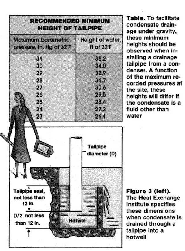
Condensate removal through a properly installed tailpipe is the simplest method. The minimum height for the barometric leg is based on the maximum recorded barometric pressure in the system. The table on p. 120 illustrates the minimum tailpipe height that should be used when the system handles water; if the condensate is any fluid other than water, height adjustments must be made to account for variable fluid density.
The tailpipe arrangement is crucial. To ensure adequate discharge of the condensate, the system should not contain any horizontal runs of discharge pipe. While the ideal tailpipe arrangement is straight down, site conditions may prevent the installation of vertical pipelines. In this case, 45-deg runs of pipe are suitable, as long as the bend occurs no less than five pipe diameters (a minimum of 4 ft) away from the condensate outlet flange (Figure 2).
To collect the condensate, the tailpipe outlet is directed into a hotwell or drain· age basin. HEI standards specify seal and clearance dimensions from the tailpipe outlet to the bottom of the hotwell.
The hotwell should be sized so that the dimensions from the bottom of the tailpipe to the point of overflow in the hotwell is large enough to contain at least 1.5 times the volume of condensate contained in the minimum recommended height of the tailpipe. In no case should the seal height be less than 12 in. (Figure 3).
Shell-and-tube surface condensers may be’ installed either horizontally or vertically. The vapors to be condensed can be routed through either the inside or the outside of the tubes. However, once a unit has been designated for tubeside or shellside vapor duty, it should remain dedicated to that type of service.
The condenser must be installed to allow for complete condensate drainage. Mounting arrangements should take into account the weight of the condenser when it is fully flooded.
Vacuum Piping: Paragraph 6.3 of the Heat Exchange Institute’s Standards for Steam Jet Vacuum Systems (4th ed.) details the procedure for calculating pressure drop in vacuum systems. In general, the diameter of the piping between the process and the ejector system must be at least as large as the suction connection in the first-stage ejector. In a multiple-element ejector system, where the ejectors may be operated simultaneously, the piping area must be at least as large as the total cross-sectional area, which is determined by adding the total areas of all ejector inlet connections.
To minimize pressure drop, all piping between the process and the steam-jet vacuum system and between each successive stage of the vacuum system should have as few valves and fittings as possible, and all connections should be kept as short as possible. Wherever possible, long-radius elbows should be used, and drains must be provided in all low points to prevent condensate buildup.
When a precondenser is used, the potential pressure drop across it must be calculated, to ensure that such pressure drop will not impede system performance. The ejector manufacturer should be consulted to determine the suitability of the installation.
Utilities: Steam Supply — A source of dry steam – at or slightly above design pressures- must be available at the ejector nozzles at all times. Operating a steam-jet vacuum system at steam pressures lower than those specified in the system design will reduce system stability.
The steam should be dry and saturated, unless the system specifications call for superheated steam. To maintain the optimum velocity, and avoid excessive heat loss and pressure drop, an insulated steam lines should be sized to match the connections on the ejectors. For dry steam, the inlet line should be taken off the top of main steam header.
If moisture is present in the steam, a separator and trap should be used to improve steam quality to better than 99.5%. An ejector may work with as much as 2 or 3% moisture in the steam, but would then require greater design pressures. Poor-quality steam will not only threaten the system, but may cause erosion of the steam nozzle and diffuser.
Cooling Water Supply: The specified quantity of water must be supplied to the condenser, and it must be at or below the design temperatures. If the volume of cooling water drops, the temperature and pressure of the vapor in the condenser will rise and the system will cease to operate correctly. A temperature gage at the cooling water outlet should be used to determine the adequacy of the cooling water flow.
Condensate Removal: Since the operating pressure of the condenser is subatmospheric (under vacuum), collected condensate must be continuously removed. This may be accomplished by gravity, through a trap or a loop-seal tailpipe, or with the help of a condensate pump.
Condensate removal through a properly installed tailpipe is the simplest method. The minimum height for the barometric leg is based on the maximum recorded barometric pressure in the system. The table on p. 120 illustrates the minimum tailpipe height that should be used when the system handles water; if the condensate is any fluid other than water, height adjustments must be made to account for variable fluid density.
The tailpipe arrangement is crucial. To ensure adequate discharge of the condensate, the system should not contain any horizontal runs of discharge pipe. While the ideal tailpipe arrangement is straight down, site conditions may prevent the installation of vertical pipelines. In this case, 45-deg runs of pipe are suitable, as long as the bend occurs no less than five pipe diameters (a minimum of 4 ft) away from the condensate outlet flange (Figure 2).
To collect the condensate, the tailpipe outlet is directed into a hotwell or drain· age basin. HEI standards specify seal and clearance dimensions from the tailpipe outlet to the bottom of the hotwell.
The hotwell should be sized so that the dimensions from the bottom of the tailpipe to the point of overflow in the hotwell is large enough to contain at least 1.5 times the volume of condensate contained in the minimum recommended height of the tailpipe. In no case should the seal height be less than 12 in. (Figure 3).
 In situations where minimum height requirements for a barometric leg cannot be accommodated, a low-level condensate- removal system can be added (Figure 4). This will increase the complexity of the system, since it involves adding a condensate pump, a liquid level control in the collection tank, and a control valve.
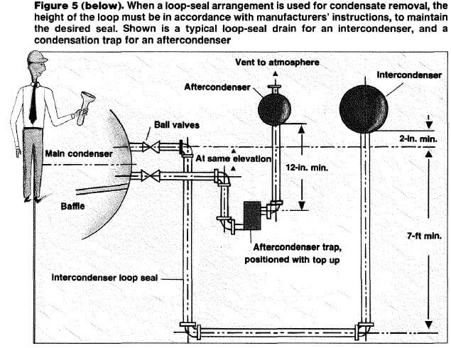
 If during condensate removal the condensate is returned to a collection tank operating at a pressure lower than the condenser, a loop-seal arrangement can be used to facilitate condensate removal from the system (Figure 5). This application is typically used with a turbine exhaust condenser.
 Troubleshooting Tips: There are two basic types of malfunction in an ejector system: those caused by external influences or equipment, and those caused by the ejectors or condensers themselves. It is important that only qualified personnel, using proper equipment, perform testing.
External Problems – To locate the source:
Troubleshooting Tips: There are two basic types of malfunction in an ejector system: those caused by external influences or equipment, and those caused by the ejectors or condensers themselves. It is important that only qualified personnel, using proper equipment, perform testing.
External Problems – To locate the source:
 Suction Control: A given steam-jet system has a fixed performance curve of capacity (lb/h) vs. absolute suction pressure (mm or in. Hg absolute). Therefore, a given capacity can be obtained by controlling the suction pressure. Several methods are described below.
Using a control valve, an artificial load can be taken from the discharge of any one of the ejectors in the system to produce a recycle control loop. To avoid vacuum leaks, care should be taken in both the sizing and the installation of this control valve (between two levels of vacuum).
The load could also be taken from an external source, such as an atmospheric air bleed, steam bleed from the utility steam, or other process flu- ids. Condensable vapors are preferred, as their load on subsequent ejector stages can be minimized in the first intercondenser.
In a competing method, a valve can be used in the suction line, to create an artificial pressure drop across the ejector. This scheme works well when flow through the suction line is sufficient to cause a pressure drop across the valve’s restricted flow area. When actual flow through the suction line is at least 50% of the design flow, such an artificial pressure drop can usually be induced.
The addition of a valve in the suction line is also useful to isolate the vacuum system during startup, shutdown, and troubleshooting. In the event of a vacuum system failure, such a valve can also protect a water-sensitive process, by preventing steam or condensate from flowing back into the suction line.
The performance curve of a multistage ejector system varies according to the number of operating stages, and will therefore produce different levels of vacuum with on-off control of select ejector stages. To control suction, successive stages may only be turned off, starting in succession from the first stage (that which is nearest the process) to the last one (that which discharges to the atmosphere).
A single stage operating alone will produce pressures in the range of about 50 mm Hg absolute up to atmospheric pressure. Two stages will produce pressures between 10 mm and 100 mm, while three stages will produce between 1 mm and 25 mm.
Finally, suction pressure can be controlled by bringing the whole system in parallel on or off line, or by turning on and off individual ejector elements that have been installed in parallel to the primary stage and use the same interconnections. To isolate individual elements from the process, a valve must be installed in the steam line to that jet, and in the suction line. A discharge valve may also be added to allow the element to be completely isolated from the system and to be removed for servicing.
According to HEI Standards (Paragraph 4.2.2.4.1), the design pressure of the suction chamber and diffuser must be no more than 15 psig (internal), and the unit should be able to withstand full vacuum, unless otherwise specified. During operation, care must be taken when using a discharge valve to avoid pressurizing the ejector bodies with mainline steam pressure. To ensure that this does not happen, the suction valve should be closed first, followed by the steam valve, and then the discharge valve (use the opposite sequence when turning the system on).
If this procedure cannot be guaranteed, then a pressure-relief valve should be used. It should be sized for the steam consumption of the ejector, plus an additional 40%. According to HEI standards (Paragraph 4.1.7.2), the valves should be set to relieve the pressure when it exceeds 15 psig.
Instrumentation: In a steam-jet vacuum system, the type of instruments, gages and flowmeters used for flow control depend on the specific system being used. Ejector manufacturers should provide critical design data, as well as guidance in selecting and installing the instrumentation.
The basic steam-jet vacuum system requires a pressure gage in the main steam line. Typically installed just ahead of the steam-jet system, this gage monitors system performance, and indicates when there is a departure from design pressure.
A steam-pressure gage can be installed on each ejector, when ejectors must be turned on and off for control or troubleshooting. Such a gage array will guarantee that each stage of a multistage system is supplied with the correct steam pressure.
Pressure gages may also be useful over time if the mainline steam pres sure varies over the system and must be controlled at each ejector. Such gages are helpful during troubleshooting, since they may indicate plugged steam lines or nozzles, or faulty valves.
A flowmeter can be added to maintain the specified flow to the condenser. Water-temperature gages on the inlet and outlet water lines of each shell and tube condenser will indicate when the maximum outlet temperature has been exceeded, which may demonstrate insufficient water or excess steam load. Such gages will also alert the operator to a decrease in the temperature, which may indicate a fouled condition.
Most systems will include a vacuum gage to monitor absolute pressure at the process vessel. This gage may not be able to measure the pressure of the overall vacuum system, since other devices may be inline between the two.
When troubleshooting a multistage steam-jet system, it is desirable to have suction pressure measured at each ejector. In these situations, a portable vacuum gage is helpful.
There are many self-compensating, absolute-pressure gages available. Users are cautioned against relying on a compound, bourdon-tube type gage, which will not give accurate results for vacuum levels over 28-in. Hg. If a mercury manometer is used, it must be corrected for actual barometric pressure.
Packaging: The components of a steam-jet vacuum system can be conveniently packaged or skid mounted. The package can be a simple arrangement that includes valves, interconnecting piping and utility connections, or it can be a more complex assembly, such as a complete turnkey system.
Modular packaging of a steam-jet assembly must be designed so that forces and moments are ultimately transferred to support points. If loads are not transferred safely to suitable anchorage points, a failure or misalignment of the equipment can occur. In particular, external pipe connections should not impose any additional forces or moments to the steam, vapor and water piping.
Authors: John Aglitz, Rajender K. Bhatnagar, David B. Birgenheier, Donald E. Bolt, Thomas L. Butzbach, Russell E. Ojala
Edited By: Suzanne Shelley
Suction Control: A given steam-jet system has a fixed performance curve of capacity (lb/h) vs. absolute suction pressure (mm or in. Hg absolute). Therefore, a given capacity can be obtained by controlling the suction pressure. Several methods are described below.
Using a control valve, an artificial load can be taken from the discharge of any one of the ejectors in the system to produce a recycle control loop. To avoid vacuum leaks, care should be taken in both the sizing and the installation of this control valve (between two levels of vacuum).
The load could also be taken from an external source, such as an atmospheric air bleed, steam bleed from the utility steam, or other process flu- ids. Condensable vapors are preferred, as their load on subsequent ejector stages can be minimized in the first intercondenser.
In a competing method, a valve can be used in the suction line, to create an artificial pressure drop across the ejector. This scheme works well when flow through the suction line is sufficient to cause a pressure drop across the valve’s restricted flow area. When actual flow through the suction line is at least 50% of the design flow, such an artificial pressure drop can usually be induced.
The addition of a valve in the suction line is also useful to isolate the vacuum system during startup, shutdown, and troubleshooting. In the event of a vacuum system failure, such a valve can also protect a water-sensitive process, by preventing steam or condensate from flowing back into the suction line.
The performance curve of a multistage ejector system varies according to the number of operating stages, and will therefore produce different levels of vacuum with on-off control of select ejector stages. To control suction, successive stages may only be turned off, starting in succession from the first stage (that which is nearest the process) to the last one (that which discharges to the atmosphere).
A single stage operating alone will produce pressures in the range of about 50 mm Hg absolute up to atmospheric pressure. Two stages will produce pressures between 10 mm and 100 mm, while three stages will produce between 1 mm and 25 mm.
Finally, suction pressure can be controlled by bringing the whole system in parallel on or off line, or by turning on and off individual ejector elements that have been installed in parallel to the primary stage and use the same interconnections. To isolate individual elements from the process, a valve must be installed in the steam line to that jet, and in the suction line. A discharge valve may also be added to allow the element to be completely isolated from the system and to be removed for servicing.
According to HEI Standards (Paragraph 4.2.2.4.1), the design pressure of the suction chamber and diffuser must be no more than 15 psig (internal), and the unit should be able to withstand full vacuum, unless otherwise specified. During operation, care must be taken when using a discharge valve to avoid pressurizing the ejector bodies with mainline steam pressure. To ensure that this does not happen, the suction valve should be closed first, followed by the steam valve, and then the discharge valve (use the opposite sequence when turning the system on).
If this procedure cannot be guaranteed, then a pressure-relief valve should be used. It should be sized for the steam consumption of the ejector, plus an additional 40%. According to HEI standards (Paragraph 4.1.7.2), the valves should be set to relieve the pressure when it exceeds 15 psig.
Instrumentation: In a steam-jet vacuum system, the type of instruments, gages and flowmeters used for flow control depend on the specific system being used. Ejector manufacturers should provide critical design data, as well as guidance in selecting and installing the instrumentation.
The basic steam-jet vacuum system requires a pressure gage in the main steam line. Typically installed just ahead of the steam-jet system, this gage monitors system performance, and indicates when there is a departure from design pressure.
A steam-pressure gage can be installed on each ejector, when ejectors must be turned on and off for control or troubleshooting. Such a gage array will guarantee that each stage of a multistage system is supplied with the correct steam pressure.
Pressure gages may also be useful over time if the mainline steam pres sure varies over the system and must be controlled at each ejector. Such gages are helpful during troubleshooting, since they may indicate plugged steam lines or nozzles, or faulty valves.
A flowmeter can be added to maintain the specified flow to the condenser. Water-temperature gages on the inlet and outlet water lines of each shell and tube condenser will indicate when the maximum outlet temperature has been exceeded, which may demonstrate insufficient water or excess steam load. Such gages will also alert the operator to a decrease in the temperature, which may indicate a fouled condition.
Most systems will include a vacuum gage to monitor absolute pressure at the process vessel. This gage may not be able to measure the pressure of the overall vacuum system, since other devices may be inline between the two.
When troubleshooting a multistage steam-jet system, it is desirable to have suction pressure measured at each ejector. In these situations, a portable vacuum gage is helpful.
There are many self-compensating, absolute-pressure gages available. Users are cautioned against relying on a compound, bourdon-tube type gage, which will not give accurate results for vacuum levels over 28-in. Hg. If a mercury manometer is used, it must be corrected for actual barometric pressure.
Packaging: The components of a steam-jet vacuum system can be conveniently packaged or skid mounted. The package can be a simple arrangement that includes valves, interconnecting piping and utility connections, or it can be a more complex assembly, such as a complete turnkey system.
Modular packaging of a steam-jet assembly must be designed so that forces and moments are ultimately transferred to support points. If loads are not transferred safely to suitable anchorage points, a failure or misalignment of the equipment can occur. In particular, external pipe connections should not impose any additional forces or moments to the steam, vapor and water piping.
Authors: John Aglitz, Rajender K. Bhatnagar, David B. Birgenheier, Donald E. Bolt, Thomas L. Butzbach, Russell E. Ojala
Edited By: Suzanne Shelley
Since the capacity of a single ejector is fixed by its dimensions, a single unit has practical limits on the total compression and throughput it can deliver. For greater compression, two or more ejectors can be arranged in series. For greater throughput capacity of gas or vapor, two or more ejectors can be arranged in parallel.
In a multi-stage system, condensers are typically used between successive ejectors. By condensing the vapors before sending the stream on to the next stage, the vapor load is reduced. This allows smaller ejectors to be used, and reduces steam consumption.
Precondensers can be added to reduce the load on the first-stage ejector, and allow for a smaller unit. An aftercondenser can also be added, to condense vapors from the final stage. Adding an aftercondenser will not affect overall system performance, but may ease disposal of vapors.
Ejectors may be installed at any angle. However, to keep condensate and any entrained solids from collecting, low points in the vacuum piping system should be avoided during design and installation.
Provisions should be made to ensure proper drainage of the ejector bodies, since any condensed steam or process vapors may reduce throughput capacity. Drain valves installed at low points can be either manual or automatic, depending on customer requirements, and the drain cycle must relate to the type of process: Batch systems should be drained before each cycle, while continuous processes may be drained during operation if needed.
In most cases, the ejector is an integral part of a steam-jet vacuum system, but it is not intended to provide physical support for the system. Adequate piping support should be provided to minimize external loads on the ejectors, since any misalignment will adversely affect system performance. In fact, care must be exercised during system design, so that external loads caused by thermal movement and mechanical loading are minimized.
If the ejector or piping is steam jacketed to prevent ice buildup, its orientation will affect the operation and drainage of the jackets. To keep the jackets from filling with condensate, all inlet and outlet piping should be installed so that the jacket can be sufficiently drained.
In certain systems, vacuum processes produce varying amounts of solid carryover, which can deposit inside the ejector system. During ejector placement, access for cleaning must be maintained, especially if the potential for deposits exists.
Condensers
In multi-stage systems, intercondensers are used between successive ejector stages to reduce the vapor load on later stages. These units condense steam and condensable vapors, and cool air and other non-condensable vapors. Typically, a steam-jet vacuum system uses either a direct contact (or barometric) condenser, or a surface condenser, typically a shell-and-tube heat exchanger.
For optimal performance, direct-contact condensers must be installed upright and plumb. When the condenser is mounted at barometric elevation (Table, p. 120), drainage by gravity is induced through a sealed tailpipe or drainage leg. Such a condenser must be placed at a height that is sufficient to prevent flooding under normal operation. Water inlet and outlet piping must be sized according to design flow rates.
In a direct-contact condenser, the drainage lines or tailpipes should be installed vertically, and should run to a hotwell or seal tank (Figure 2). All tailpipes connected to inter- and aftercondensers must run separately to the hotwell to prevent recirculation of noncondensable vapors. Condensate removal is discussed below.
Shell-and-tube surface condensers may be’ installed either horizontally or vertically. The vapors to be condensed can be routed through either the inside or the outside of the tubes. However, once a unit has been designated for tubeside or shellside vapor duty, it should remain dedicated to that type of service.
The condenser must be installed to allow for complete condensate drainage. Mounting arrangements should take into account the weight of the condenser when it is fully flooded.
Vacuum Piping: Paragraph 6.3 of the Heat Exchange Institute’s Standards for Steam Jet Vacuum Systems (4th ed.) details the procedure for calculating pressure drop in vacuum systems. In general, the diameter of the piping between the process and the ejector system must be at least as large as the suction connection in the first-stage ejector. In a multiple-element ejector system, where the ejectors may be operated simultaneously, the piping area must be at least as large as the total cross-sectional area, which is determined by adding the total areas of all ejector inlet connections.
To minimize pressure drop, all piping between the process and the steam-jet vacuum system and between each successive stage of the vacuum system should have as few valves and fittings as possible, and all connections should be kept as short as possible. Wherever possible, long-radius elbows should be used, and drains must be provided in all low points to prevent condensate buildup.
When a precondenser is used, the potential pressure drop across it must be calculated, to ensure that such pressure drop will not impede system performance. The ejector manufacturer should be consulted to determine the suitability of the installation.
Utilities: Steam Supply — A source of dry steam – at or slightly above design pressures- must be available at the ejector nozzles at all times. Operating a steam-jet vacuum system at steam pressures lower than those specified in the system design will reduce system stability.
The steam should be dry and saturated, unless the system specifications call for superheated steam. To maintain the optimum velocity, and avoid excessive heat loss and pressure drop, an insulated steam lines should be sized to match the connections on the ejectors. For dry steam, the inlet line should be taken off the top of main steam header.
If moisture is present in the steam, a separator and trap should be used to improve steam quality to better than 99.5%. An ejector may work with as much as 2 or 3% moisture in the steam, but would then require greater design pressures. Poor-quality steam will not only threaten the system, but may cause erosion of the steam nozzle and diffuser.
Cooling Water Supply: The specified quantity of water must be supplied to the condenser, and it must be at or below the design temperatures. If the volume of cooling water drops, the temperature and pressure of the vapor in the condenser will rise and the system will cease to operate correctly. A temperature gage at the cooling water outlet should be used to determine the adequacy of the cooling water flow.
Condensate Removal: Since the operating pressure of the condenser is subatmospheric (under vacuum), collected condensate must be continuously removed. This may be accomplished by gravity, through a trap or a loop-seal tailpipe, or with the help of a condensate pump.
Condensate removal through a properly installed tailpipe is the simplest method. The minimum height for the barometric leg is based on the maximum recorded barometric pressure in the system. The table on p. 120 illustrates the minimum tailpipe height that should be used when the system handles water; if the condensate is any fluid other than water, height adjustments must be made to account for variable fluid density.
The tailpipe arrangement is crucial. To ensure adequate discharge of the condensate, the system should not contain any horizontal runs of discharge pipe. While the ideal tailpipe arrangement is straight down, site conditions may prevent the installation of vertical pipelines. In this case, 45-deg runs of pipe are suitable, as long as the bend occurs no less than five pipe diameters (a minimum of 4 ft) away from the condensate outlet flange (Figure 2).
To collect the condensate, the tailpipe outlet is directed into a hotwell or drain· age basin. HEI standards specify seal and clearance dimensions from the tailpipe outlet to the bottom of the hotwell.
The hotwell should be sized so that the dimensions from the bottom of the tailpipe to the point of overflow in the hotwell is large enough to contain at least 1.5 times the volume of condensate contained in the minimum recommended height of the tailpipe. In no case should the seal height be less than 12 in. (Figure 3).
In situations where minimum height requirements for a barometric leg cannot be accommodated, a low-level condensate- removal system can be added (Figure 4). This will increase the complexity of the system, since it involves adding a condensate pump, a liquid level control in the collection tank, and a control valve.
If during condensate removal the condensate is returned to a collection tank operating at a pressure lower than the condenser, a loop-seal arrangement can be used to facilitate condensate removal from the system (Figure 5). This application is typically used with a turbine exhaust condenser.
Troubleshooting Tips: There are two basic types of malfunction in an ejector system: those caused by external influences or equipment, and those caused by the ejectors or condensers themselves. It is important that only qualified personnel, using proper equipment, perform testing.
External Problems – To locate the source:
- Determine whether any changes have been made to the process served by the steam-jet vacuum system
- Determine whether the pressure and temperature of the steam or the condensing water have changed with respect to system specifications
- Determine whether any recent process changes have been made, which may have altered the feed rate of the vapor stream evacuated from the process vessel
- Determine whether the problem developed gradually or suddenly. As a general rule, a gradual loss of vacuum is due to changes or the deterioration of the vacuum system, while a sudden loss of vacuum usually is due to a change in utilities, increase in backpressure, or system leak
- Review the unit’s recent maintenance history, and make note of any recent modifications
- Review any records of previous problems
- Single-stage ejector 50 mm Hg absolute (A)
- Two-stage ejector 4-1 0 mm HgA
- Three-stage ejector 0.8-1.55 mm HgA
- Four-stage ejector 0.1-0.2 mm HgA
- Five-stage ejector 0.01-0.02 mm HgA
- Six-stage ejector 0.001-0.003 mm HgA
Suction Control: A given steam-jet system has a fixed performance curve of capacity (lb/h) vs. absolute suction pressure (mm or in. Hg absolute). Therefore, a given capacity can be obtained by controlling the suction pressure. Several methods are described below.
Using a control valve, an artificial load can be taken from the discharge of any one of the ejectors in the system to produce a recycle control loop. To avoid vacuum leaks, care should be taken in both the sizing and the installation of this control valve (between two levels of vacuum).
The load could also be taken from an external source, such as an atmospheric air bleed, steam bleed from the utility steam, or other process flu- ids. Condensable vapors are preferred, as their load on subsequent ejector stages can be minimized in the first intercondenser.
In a competing method, a valve can be used in the suction line, to create an artificial pressure drop across the ejector. This scheme works well when flow through the suction line is sufficient to cause a pressure drop across the valve’s restricted flow area. When actual flow through the suction line is at least 50% of the design flow, such an artificial pressure drop can usually be induced.
The addition of a valve in the suction line is also useful to isolate the vacuum system during startup, shutdown, and troubleshooting. In the event of a vacuum system failure, such a valve can also protect a water-sensitive process, by preventing steam or condensate from flowing back into the suction line.
The performance curve of a multistage ejector system varies according to the number of operating stages, and will therefore produce different levels of vacuum with on-off control of select ejector stages. To control suction, successive stages may only be turned off, starting in succession from the first stage (that which is nearest the process) to the last one (that which discharges to the atmosphere).
A single stage operating alone will produce pressures in the range of about 50 mm Hg absolute up to atmospheric pressure. Two stages will produce pressures between 10 mm and 100 mm, while three stages will produce between 1 mm and 25 mm.
Finally, suction pressure can be controlled by bringing the whole system in parallel on or off line, or by turning on and off individual ejector elements that have been installed in parallel to the primary stage and use the same interconnections. To isolate individual elements from the process, a valve must be installed in the steam line to that jet, and in the suction line. A discharge valve may also be added to allow the element to be completely isolated from the system and to be removed for servicing.
According to HEI Standards (Paragraph 4.2.2.4.1), the design pressure of the suction chamber and diffuser must be no more than 15 psig (internal), and the unit should be able to withstand full vacuum, unless otherwise specified. During operation, care must be taken when using a discharge valve to avoid pressurizing the ejector bodies with mainline steam pressure. To ensure that this does not happen, the suction valve should be closed first, followed by the steam valve, and then the discharge valve (use the opposite sequence when turning the system on).
If this procedure cannot be guaranteed, then a pressure-relief valve should be used. It should be sized for the steam consumption of the ejector, plus an additional 40%. According to HEI standards (Paragraph 4.1.7.2), the valves should be set to relieve the pressure when it exceeds 15 psig.
Instrumentation: In a steam-jet vacuum system, the type of instruments, gages and flowmeters used for flow control depend on the specific system being used. Ejector manufacturers should provide critical design data, as well as guidance in selecting and installing the instrumentation.
The basic steam-jet vacuum system requires a pressure gage in the main steam line. Typically installed just ahead of the steam-jet system, this gage monitors system performance, and indicates when there is a departure from design pressure.
A steam-pressure gage can be installed on each ejector, when ejectors must be turned on and off for control or troubleshooting. Such a gage array will guarantee that each stage of a multistage system is supplied with the correct steam pressure.
Pressure gages may also be useful over time if the mainline steam pres sure varies over the system and must be controlled at each ejector. Such gages are helpful during troubleshooting, since they may indicate plugged steam lines or nozzles, or faulty valves.
A flowmeter can be added to maintain the specified flow to the condenser. Water-temperature gages on the inlet and outlet water lines of each shell and tube condenser will indicate when the maximum outlet temperature has been exceeded, which may demonstrate insufficient water or excess steam load. Such gages will also alert the operator to a decrease in the temperature, which may indicate a fouled condition.
Most systems will include a vacuum gage to monitor absolute pressure at the process vessel. This gage may not be able to measure the pressure of the overall vacuum system, since other devices may be inline between the two.
When troubleshooting a multistage steam-jet system, it is desirable to have suction pressure measured at each ejector. In these situations, a portable vacuum gage is helpful.
There are many self-compensating, absolute-pressure gages available. Users are cautioned against relying on a compound, bourdon-tube type gage, which will not give accurate results for vacuum levels over 28-in. Hg. If a mercury manometer is used, it must be corrected for actual barometric pressure.
Packaging: The components of a steam-jet vacuum system can be conveniently packaged or skid mounted. The package can be a simple arrangement that includes valves, interconnecting piping and utility connections, or it can be a more complex assembly, such as a complete turnkey system.
Modular packaging of a steam-jet assembly must be designed so that forces and moments are ultimately transferred to support points. If loads are not transferred safely to suitable anchorage points, a failure or misalignment of the equipment can occur. In particular, external pipe connections should not impose any additional forces or moments to the steam, vapor and water piping.
Authors: John Aglitz, Rajender K. Bhatnagar, David B. Birgenheier, Donald E. Bolt, Thomas L. Butzbach, Russell E. Ojala
Edited By: Suzanne Shelley