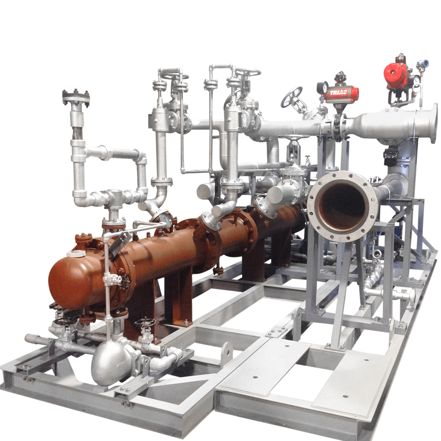
Steam Jet Ejector Vacuum System
Steam Jet Ejector Vacuum System
Reliable Vacuum Service for the Process Industries
About
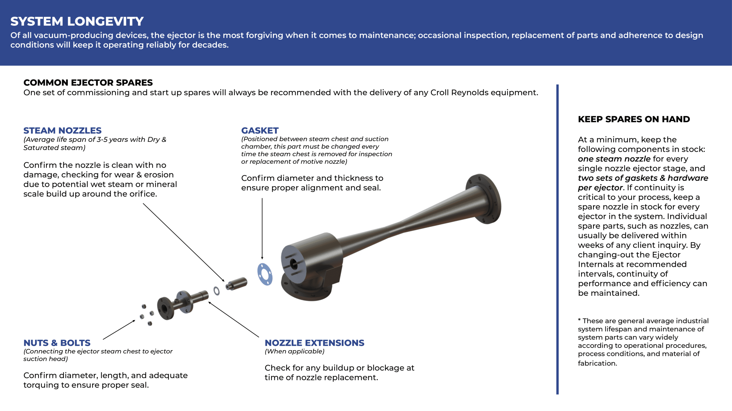
Ejector vacuum systems offer a reliable and economical means of handling and compressing low to high flow gas streams at high, medium, and low levels of vacuum. A vacuum system usually consists of two main components: Ejectors and Condensers. The most critical component of a vacuum system is the ejector, and it consists of four main parts: the steam chest, steam nozzle/s, suction head, and diffuser.
Condensers are heat transfer device that promotes condensation. Condensers are designed for removing/exchanging heat between a hot fluid and coolant. There are two main types of condensers used in vacuum systems: Direct contact condensers (aka “mixing” or “Barometric”) and Surface condensers (aka “non-mixing” or “shell and tube”). Condensers are normally situated between ejector stages to collect and capture condensable liquid and particles in the stream. This reduces the vapor load handled by each successive ejector, thereby improving overall system efficiency. The number of ejector stages in each design can range from one to six, the number of stages is determined by the level of vacuum required. The number of condenser stages in each design is dependent on the temperature of the cooling fluid at the inlet of the first stage’s condenser.
Advantages
These are the primary advantages of installing ejectors versus mechanical pumps for high-volume, low-pressure applications.
- Reliable, consistent service and output
- Handles high volumes of gasses and vapors
- Handles condensable loads that contain liquids and particulate
- No moving parts
- Low initial cost (compared to mechanical pumps)
- Easy to install and maintain
- Easy to retrofit or upgrade
- Long-lasting and durable equipment
- Can be constructed from a wide variety of steel, alloy, and composite materials including thermoplastics such as PP, PTFE, and PVDF.
How it works
Ejectors use converging-diverging nozzle technology to convert potential energy into kinetic energy. These energy transfers operate according to the jet vacuum principle, which illustrates the inverse relationship of potential and kinetic energy in supersonic, sonic, or subsonic flows; as the velocity of a moving fluid (liquid or gas) increases, the pressure within the fluid decreases. When the pressure energy (aka potential energy) of low-velocity steam flows through a nozzle, the result is high-velocity, low-pressure steam.
The momentum of this supersonic, saturated steam forces displacement in the steam chest as it exits the nozzle. In this scenario steam is the “motive fluid” that creates a localized vacuum in the steam chest (aka suction chamber).
The low-pressure region within the steam chest then entrains a “suction fluid” (process vapor and or/air) through a connecting inlet. The high velocity motive fluid and low-pressure suction fluid mix freely as they flow through the diffuser, where the mixture experiences a shockwave transition back to a subsonic state.
By temporarily reducing the stream’s momentum, this change in velocity creates another, subsequent increase in pressure to propel the combined stream into the next stage of the vacuum system. The internal geometry, precise dimensions, and arrangement of ejector components are expertly engineered to govern velocity/pressure conversions.
The diffuser’s geometry moderates the outflow conditions of the mixed stream to discharge for the ejector stage. The diffuser’s output is then available to be cooled, condensed, and pumped through a condenser, compressing the fluids so that the motive energy can be utilized in compressing the process vapors to the final discharge pressure required at the final stage of the vacuum system. In the last stage of an ejector system, any remaining vapors at the discharge stage have been treated for environmentally safe release into the atmosphere.
Use cases
- Chemical –product distillation, drying, flash cooling and more
- Oil and Gas – refinery processes, product distillation and more
- Power Plants – removal of non-condensable gas for turbine efficiency
- Steel – refinery processes, product degassing and more
- Pharmaceuticals – controlled conditions for chemical processes
- Food and Beverage – product crystallization, evaporation and more