Process-powered Vacuum System
Process-powered Vacuum System
Solutions for handling organic gasses and vapors in fine chemical applications
About
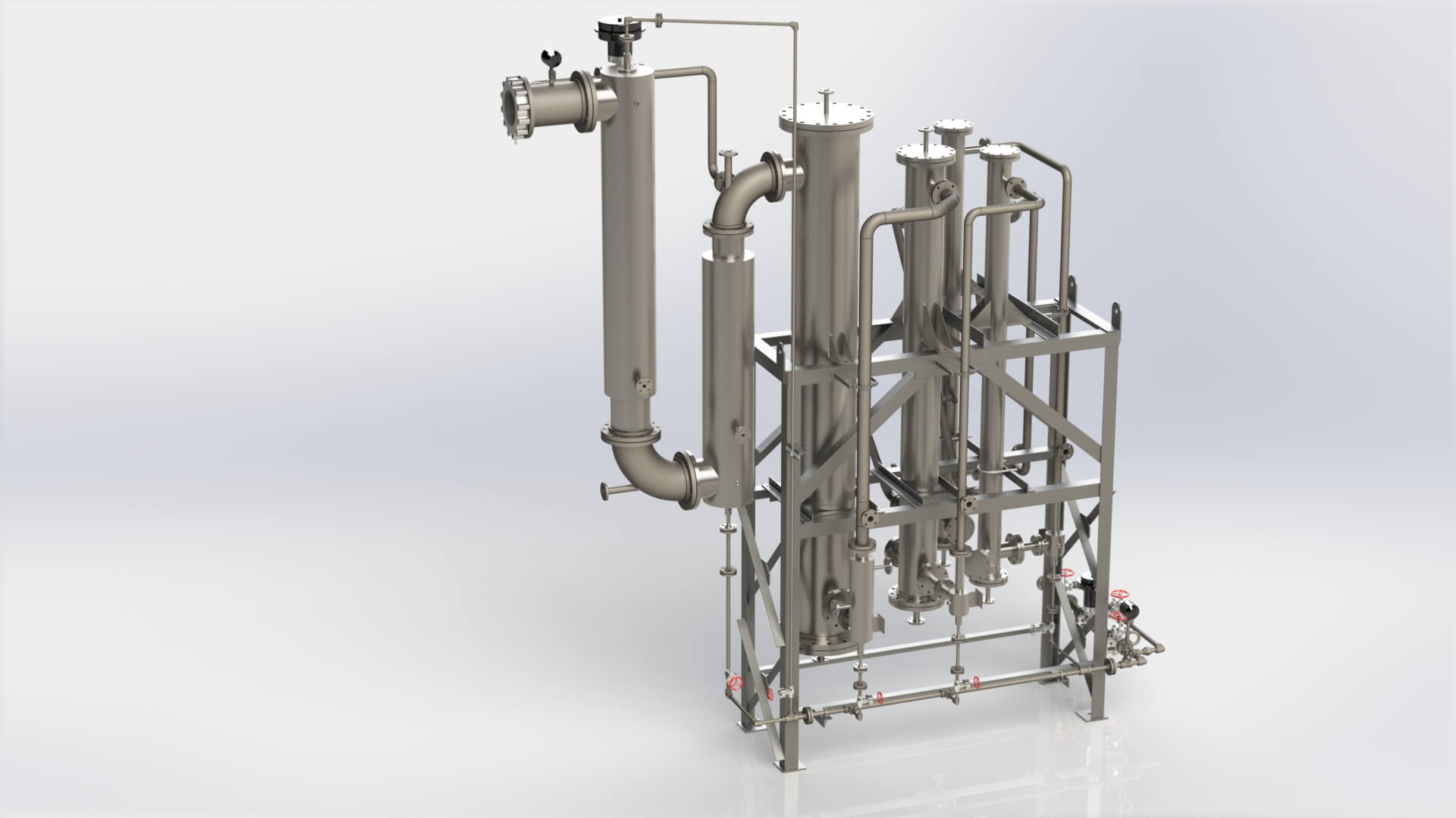
Process-powered vacuum systems offers a reliable and economical means of handling and compressing process vapor at different vacuum levels (high, medium, and low) while recovering valuable process components which can’t be contaminated with steam/water. A process-powered vacuum system is commonly driven by motive fluids such as mono-chlorobenzene, phenols, glycols, ethylene, and hexane. This type of vacuum system normally consists of ejectors, vaporizing systems, piping, condensers, pumps, instrumentation, and controls.
The most critical component of this type of vacuum system, like all other vacuum systems is ejectors. The most common type of heat exchanger used in process-powered vacuum systems is Surface condenser (also known as non-mixing or shell and tube) which avoids contamination of the products intended to be recovered. Like single and multi-stage steam ejector system the number of stages in each design can vary from one to six and is mostly determined by the level of vacuum for ejectors and the maximum coolant’s operating temperature for condensers. Most process-powered systems can be designed as Ejector or Hybrid Ejector (which utilizes Liquid Ring Vacuum pumps as last stage of the vacuum package).
Advantages
- Reliable, consistent service and output
- Reduces energy consumption and overall cost of plant operations
- Handles high volumes of gases and vapors at low, medium, and high pressures
- Captures condensable valuable products without contamination
- No moving parts
- Low initial cost (compared to mechanical pumps)
- Minimal maintenance cost (compared to mechanical pumps)
- Easy to install and maintain
- Easy to retrofit or upgrade
- Can be constructed from a wide variety of steel, alloy, and composite materials including thermoplastics such as PP, PTFE, and PVDF.

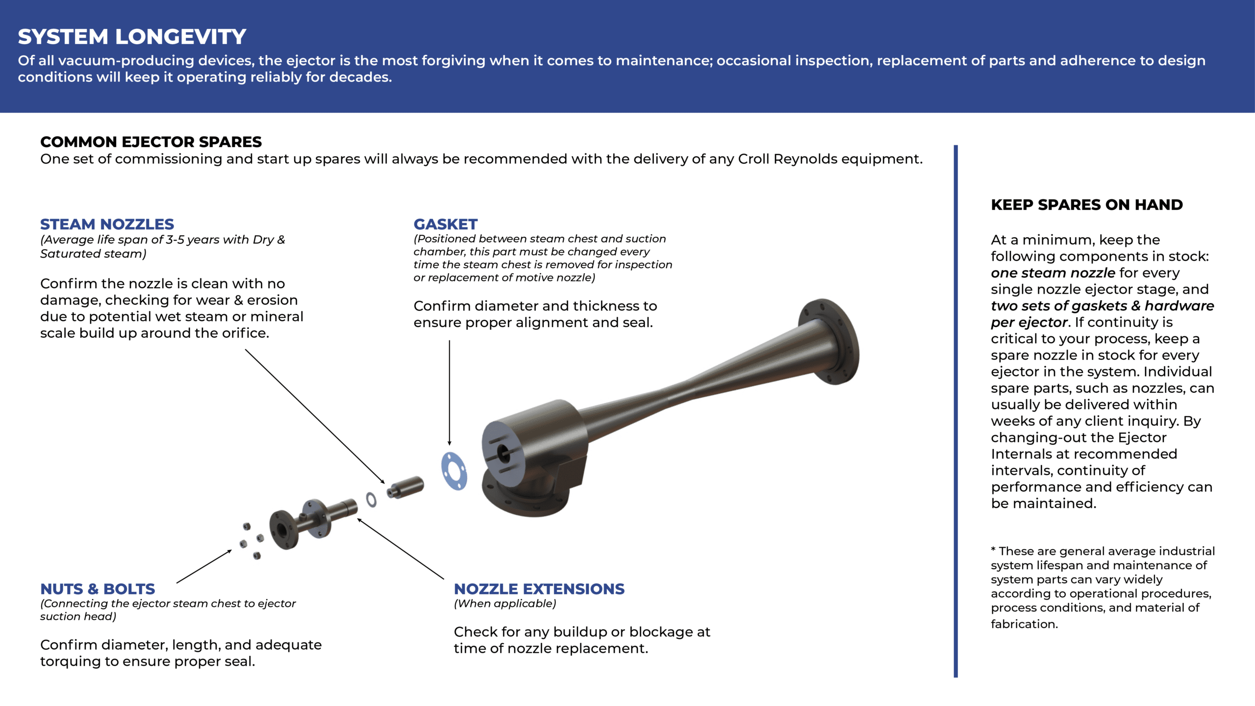
Ejectors converging-diverging nozzle technology convert the potential energy in high pressure motive fluid, in this case, mono-chlorobenzene, phenols, glycols, ethylene, and hexane, to velocity (kinetic energy) for entraining and compressing lower pressure fluid. These energy transfers operate according to the jet vacuum principle, which correlates the inverse relationship of potential-kinetic energies in supersonic, sonic, and subsonic zones. It can explain as the speed of a moving fluid (liquid or gas) increases, the pressure within the fluid decreases.
When the pressure energy (aka potential energy) of high-pressure motive fluid is converted through a converging-diverging nozzle, the result is high-velocity fluid exiting the motive nozzle at supersonic velocity. The force of this high velocity motive displaces suction fluid by creating a low-pressure region —a localized vacuum in the suction chamber—that entrains a suction fluid (i.e., process vapors) through an inlet nozzle connected to suction chamber. The high velocity motive fluid and low-pressure suction vapors mix freely as they flow through the diffuser, where the mixture experiences a shockwave and transitions back to subsonic zone by temporarily reducing the stream’s momentum; this change in velocity, creates another, subsequent increase in pressure.
The precise dimensions and arrangement of ejector components and internal geometry are expertly engineered to govern velocity/pressure conversions. The diffuser’s geometry moderates the outflow conditions of the mixed stream to discharge pressure required by the ejector stage. The diffuser’s output is then available to be cooled, condensed, and pumped through a condenser, compressing the fluids using motive energy or mechanical pump (LRVP with full recirculation arrangement) to the final discharge pressure required at the final stage of the vacuum system.
