Ejector & Vacuum System Products
our products
The highest quality guaranteed for our clients and their organizations
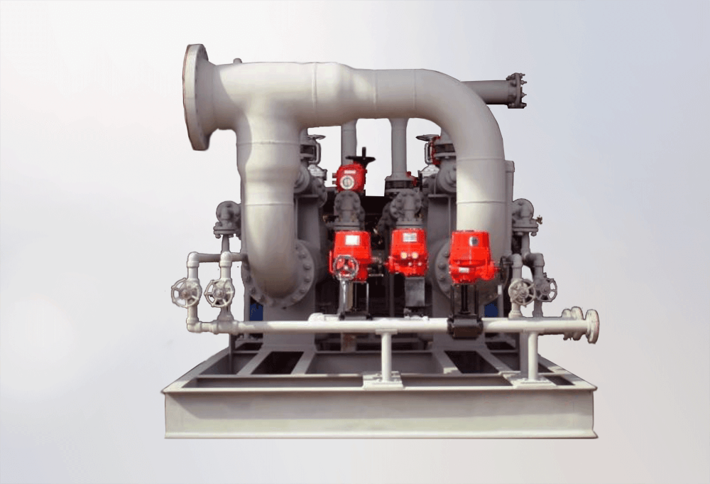
Single and Multi-stage Ejector Systems
Reliable Vacuum Service for the Process Industries
About
Ejector vacuum systems offer a reliable and economical means of handling and compressing low to high flow gas streams at high, medium, and low levels of vacuum. A vacuum system usually consists of two main components: Ejectors and Condensers. The most critical component of a vacuum system is the ejector, and it consists of four main parts: the steam chest, steam nozzle/s, suction head, and diffuser.
Condensers are a heat transfer device that promotes condensation. Condensers are designed for removing/exchanging heat between a hot fluid and coolant. There are two main types of condensers used in vacuum systems: Direct contact condensers (aka “mixing” or “Barometric”) and Surface condensers (aka “non-mixing” or “shell and tube”). Condensers are normally situated between ejector stages to collect and capture condensable liquid and particles in the stream. This reduces the vapor load handled by each successive ejector, thereby improving overall system efficiency. The number of ejector stages in each design can range from one to six, the number of stages is determined by the level of vacuum required. The number of condenser stages in each design is dependent on the temperature of the cooling fluid at the inlet of the first stage’s condenser.
Benefits and Advantages
- Reliable, consistent service and output
- Handles high volumes of gases and vapors at low, medium, and high pressures
- Handles condensable loads that contain liquids and particulate
- No moving parts
- Low initial cost (compared to mechanical pumps)
- Easy to install and maintain
- Easy to retrofit or upgrade
- Long-lasting and durable equipment
- Can be constructed from a wide variety of steel, alloy, and composite materials including thermoplastics such as PP, PTFE, and PVDF
Use cases
- Chemical processing – product distillation, drying, flash cooling, and more
- Edible Oil processing– product deodorization, decontamination, and more
- Food & Beverage processing – product crystallization, evaporation, and more
- Refinery, Oil and Gas – product distillation, Renewable Deisel, and High-Pressure Gas Flare
- Steel processing– product degassing
- Power plants – NCG removal for turbine condensers
How it works
Ejectors use converging-diverging nozzle technology to convert potential energy into kinetic energy. These energy transfers operate according to the jet vacuum principle, which illustrates the inverse relationship of potential and kinetic energy in supersonic, sonic, or subsonic flows; as the velocity of a moving fluid (liquid or gas) increases, the pressure within the fluid decreases.
When the pressure energy (aka potential energy) of low-velocity steam flows through a nozzle, the result is high-velocity, low-pressure steam. The momentum of this supersonic, saturated steam forces displacement in the steam chest as it exits the nozzle. In this scenario, steam is the “motive fluid” that creates a localized vacuum in the steam chest (aka suction chamber). The low-pressure region within the steam chest then entrains a “suction fluid” (process vapor and or/air) through a connecting inlet. The high-velocity motive fluid and low-pressure suction fluid mix freely as they flow through the diffuser, where the mixture experiences a shockwave transition back to a subsonic state. By temporarily reducing the stream’s momentum, this change in velocity creates another, subsequent increase in pressure to propel the combined stream into the next stage of the vacuum system.
The internal geometry, precise dimensions, and arrangement of ejector components are expertly engineered to govern velocity/pressure conversions. The diffuser’s geometry moderates the outflow conditions of the mixed stream to discharge pressure required for the ejector stage. The diffuser’s output is then available to be cooled, condensed, and pumped through a condenser, compressing the fluids so that the motive energy can be utilized in compressing the process vapors to the final discharge pressure required at the final stage of the vacuum system.
In the last stage of an ejector system, any remaining vapors at the discharge stage have been treated for environmentally safe release into the atmosphere.
Read more
- Steam Ejector Animation
- Steam Ejector Fundamentals
- Designing Steam Jet Vacuum Systems
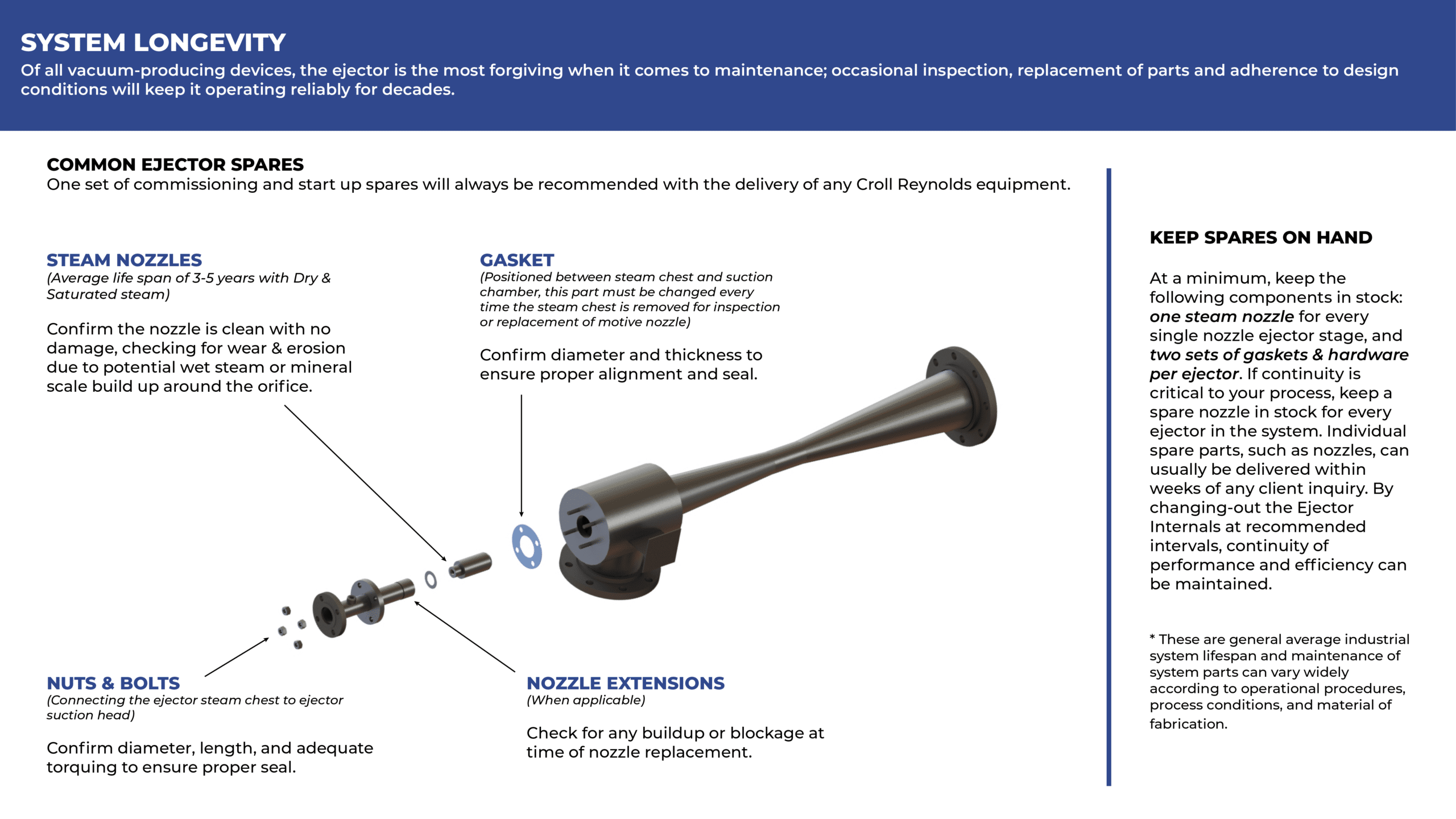
- Operation and Maintenance of Ejectors
- Keep Steam Ejectors On-line
HYBRID SYSTEMS
Similar Capacity At Improved Energy Efficiency
A hybrid system incorporates single or two-stage liquid ring vacuum pumps into a multistage ejector system with intercondensers. Liquid ring pumps can be configured for a once through or recirculating seal liquid operations. The liquid ring pump consumes electrical power instead of steam pressure to raise discharge pressure from the deep vacuum ejectors to atmospheric pressures.
Benefits and Advantages
These are the primary advantages of installing Hybrid systems of mechanical or traditional multistage systems:
- Reduced utility consumption.
- Operates using lower pressures steam
- Can be installed at ground level
How it works
The Liquid Ring vacuum pumps are rotating positive displacement pumps which can be used to replace the last stage or last two stages of ejectors in a system. The intercondensers cool the discharge from each stage of ejectors to remove condensable gases from the system by either direct contact cooling (barometric heat exchangers) or indirect cooling (shell and tube heat exchangers). The performance of a liquid ring vacuum pump is limited by the temperature of the fluid used for the liquid seal.
Liquid ring pumps require a non-condensable load to prevent cavitation and damage to the impeller of the pumps. Vacuum breaker valves are installed on Liquid ring pumps to prevent this by allowing air into the suction of the pump if the vacuum at the suction o the pump gets too deep.
Systems that utilize liquid ring vacuum pumps can use lower pressure steam to achieve the desired vacuum. Steam pressure has a diminished impact on the required mass flow to achieve vacuum at lower suction pressures. As a result of replacing the stages of the system which work at higher pressure, closer to atmospheric pressure, with a liquid ring vacuum pump, lower pressure steam can be utilized by the deeper vacuum stage ejectors without major impact on system performance.
Use cases
- Chemical processing – product distillation, fume scrubbing, and more
- Edible Oil processing – product deodorization, decontamination, and more
- Food & Beverage processing – product crystallization, evaporation, and more
- Oil and Gas – product distillation
- Steel processing – product degassing
Read more
- Steam Ejector Animation
- Steam Ejector Fundamentals
- Designing Steam Jet Vacuum Systems
- Operation and Maintenance of Ejectors
- Keep Steam Ejectors On-line
THERMOCOMPRESSORS (RECOMPRESSION SYSTEMS)
Reliable Vacuum Service for the Process Industries
Thermocompressors are designed to take a fluid, typically steam, with useful heat energy but at a pressure where it cannot be useful and compress the fluid to a useful intermediate pressure using a high-pressure motive fluid.
Much like a steam ejector, Thermocompressors consist of four major components The steam chest, nozzle, nozzle holder, and diffuser (sometimes referred to as throat). Basic thermocompressors have no moving parts. Thermocompressors can be designed in single, multiple, or adjustable nozzle configurations depending on the application.
Benefits and Advantages
These are the primary advantages of installing Thermocompressors over mechanical compression system:
- Reliable, consistent service and output
- Handles high volumes of gasses and vapors
- No moving parts
- No lubricants or wear products interact with the fluids
- Low initial cost (compared to mechanical pumps)
- Can operate in very high-temperature applications
- Easy to install and maintain
- Easy to retrofit or upgrade
- Long-lasting and durable equipment
- Can be constructed from a wide variety of materials
How it works
Thermocompressors take pressure energy of a motive fluid and convert it into velocity energy before converting it back to pressure energy again. The motive fluid is piped into a steam chest and expanded through a converging-diverging nozzle. This high-velocity steam entrains the steam entering the suction inlet and the mixed fluids are then compressed to an intermediate pressure as they pass through the diffuser (throat). The diffuser acts as a nozzle in reverse, reconverting velocity energy to pressure energy.
The precise dimensions and arrangement of Thermocompressors components are expertly engineered to govern velocity/pressure conversions. The diffuser’s geometry moderates the outflow conditions of the mixed stream to the end-state required by the process. Thermocompressors can be designed to achieve specific outlet conditions of mass flow rate and temperature or meet certain suction flow rates with specific suction and discharge pressures.
Use cases
- Chemical processing – product distillation, Het recovery, and more
- Paper – Used steam heat recovery
- Food & Beverage processing – Used heat recovery from multi-effect evaporators
- Oil and Gas – Heat recycling of exhaust gasses
- Power – Heat recovery of low-pressure superheated steam
Read more
- Steam Ejector Animation
- Steam Ejector Fundamentals
- Designing Steam Jet Vacuum Systems
- Operation and Maintenance of Ejectors
- Keep Steam Ejectors On-line”
Power Plant Vacuum Systems
Improving Turbine Efficiencies for Geothermal, Coal-Fired and Gas-Fired Power Plants
Croll Reynolds steam ejector and hybrid ejector-liquid ring vacuum systems find application in coal, gas and oil fired power plants as well as in nuclear and geothermal power installations.
The efficiency of steam turbines in a power plant directly correlates to the pressure of the steam that exits the turbine. A shell and tube condenser is typically installed to capture and condense steam exiting the turbine. Croll Reynolds vacuum systems installed at the condenser outlet efficiently remove non-condensable vapors and the associated water vapor from the turbine condenser and accordingly lowers the operating pressure of the condenser which increases the amount of heat available for conversion to mechanical power.
Croll Reynolds power vacuum plant systems are operating worldwide. Currently the company is involved in the design and installation of specialized vacuum systems for the global geothermal power industry with a focus on Indonesia.
The typical ejector vacuum system designed power applications is a two-stage, twin element unit having duplicate ejectors for each stage; one element running and one element on standby . An additional, “hogger,” start-up ejector is normally provided to evacuate the condenser prior to turning on the primary two stage system.
Process-Powered Vacuum Systems
Recovering Valuable Product from the Process Stream
Process-Powered ejector systems are powered by motive fluids other than steam and are packaged, closed loop systems which include ejectors, vaporizing systems, piping, condensers, pumps, instrumentation, and controls. Process-powered systems are commonly driven by monochlorobenzene, phenols, glycols, ethylene, and hexane.
These specialized multistage systems find application in fine chemical and polymer plants and are specified when valuable product can be recovered from the process stream and contamination of the process with steam/water avoided. The use of organic motives in process powered systems, instead of steam, also reduces the amount of energy required for plant operations.
Process-Powered Systems can be designed as Ejector or Hybrid Ejector – Liquid Ring Vacuum Systems.
Vacuum Chillers
Reliable Cost-Efficient Chilling
Croll Reynolds vacuum water chillers are a low cost-solution to cooling high volumes of water for the chemical, pharmaceutical, food and paper industries. With over 300 vacuum chillers online worldwide, Croll Reynolds is acknowledged as the leading designer and supplier to US, European and Asian industry. Most recently Croll Reynolds designed and constructed three of the world’s largest vacuum chillers for the Chinese chemical and petrochemical industries.
Croll Reynolds vacuum chilling equipment is also used to chill, sand and gravel during dam construction, in vegetable, fruit and grain processing and for chilling meats and vegetables.
Mechanical Design: Croll Reynolds chiller systems incorporate two, three or four multi-nozzle ejectors a chill tank with internal weirs, a two-stage ejector, piping, controls and instrumentation.
Vacuum chillers unlike mechanical chillers have no moving parts and require little or no maintenance over the lifetime of the equipment. Croll Reynolds chillers can be installed our doors. Vacuum chillers require no refrigerants, absorption solutions or lubricants for operation.
Operation: Vacuum refrigeration finds its widest application in chilling water for air conditioning, food processing, paper processing and industrial uses. Water is chilled usually to temperatures in the range of 35 to 60 degrees F., although in many processes, liquids are cooled to much lower temperatures. The drawing below shows how Croll Reynolds’s CHILL-VACTOR uses this principle in a typical water-chilling unit. Water to be chilled enters the chill tank and flows over a weir plate.
When the water comes in contact with the vacuum in the chill tank, it boils instantly. The weir distributes the water in the vacuum chamber. Heat energy is released as the water vapor expands and the water temperature is lowered. The chilled water is then removed by a barometric leg or pump. It is circulated through heat exchangers, air conditioning equipment or other process equipment and returned to the chill tank. If part or all of the water is required for process use, fresh water is fed continuously into the chill tank. In circulating systems, make-up water amounting to approximately 1% for each 10 degree F. of cooling is added.
Desuperheaters
Efficient Heat Transfer
Superheated steam is pressurized water that is at a temperature higher than the saturation. Although process steam is typically throttled and superheated for efficient distribution, it must be cooled before it is condensed and therefore it is less efficient than saturated steam for a majority of heat transfer operations. The most efficient way to reduce the superheat value of steam is to “desuperheat” it. This involves direct introduction of water into the steam stream.
Turbine bypass desuperheaters play a major role in power plant applications. Within a period of twenty-four hours, a Power Plant may be required to operate at minimum load, increase to maximum capacity for major part of the day, immediately cut back to minimum load and then back to maximum capacity. Bypass Systems permit unit-start up and unit-shutdown for critical heavy components in boilers and turbines. Bypass Valves are supplied with hydraulic, electric or pneumatic actuators as per the process requirements, along with complete control systems as an option.
There are two basic applications for bypass desuperheaters:
- When bypass systems are intermittently in operation to include startup and shutdown conditions and emergency conditions
- When bypass systems are permanently in operation, for example for process steam or heating applications.
For your vacuum system requirements, contact our US headquarters in Parsippany or our representative offices in your area.